English
 Español
 Português
 Deutsch
 한국어
한국어 日本語
日本語 Italiano
 Français
 العربية
 Türkçe
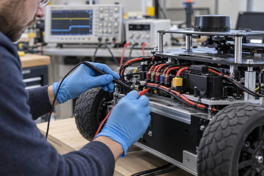
Cover image illustrates a validation workflow; it does not show an MScape product or a completed test.
Short answer: validate a robot computer on the actual DC bus, with its intended sensors and software active. Record the voltage at the computer input during boot, load changes, planned shutdown and interruption; then verify the restart state and whether useful logs survive. A brochure input-voltage range identifies a candidate computer, but it does not prove that a particular battery, harness, converter or restart sequence will work.
Why the DC bus is a system decision
A mobile robot may share power among compute, cameras, radios, drives and other loads. A bench supply can hide cable loss, converter behavior and a battery state that differs from the installed machine. Begin with the robot electrical diagram: source, protection, converter, harness length, connectors, common return and the point where voltage is measured. Keep the computer-side input separate from any downstream USB or camera supply. Motion and safety functions require their own system design and validation.
The MScape Product Brochure 2026.7.V2 lists DC 9–60 V for N100, DC 9–48 V for N203 and DC 9–60 V for N210, with automatic power-on. These are brochure-level selection inputs, not a claim about allowable transient duration, input current, inrush, connector pinout or behavior during brownout. Confirm the exact hardware revision and electrical specification with MScape before committing a harness or protection device.
Define the states to test
| State | Measure or observe | Evidence to keep |
|---|---|---|
| Cold boot | Voltage at the computer connector, start sequence, camera and network availability. | Wiring revision, oscilloscope trace or logged voltage, boot log, software and power-mode versions. |
| Idle to representative workload | Input voltage while cameras, inference, storage and network services enter their intended operating state. | Named workload, enabled peripherals, voltage trace and service-health log. |
| Other robot loads switching | Input voltage and compute/service continuity when permitted loads change state. | Load-event timestamps and the corresponding computer log. |
| Planned shutdown | Application stop, file closure and the intended power-removal sequence. | Shutdown procedure, final log entries and restart result. |
| Interrupted supply | Observed restart behavior after a controlled, approved interruption. | Test condition, outage duration, storage check and post-restart service state. |
Set pass criteria before testing. Examples include “the required camera services restart without manual intervention” or “a designated event log remains readable after the approved shutdown sequence.” These are sample requirements, not measured MScape results. Do not assume an interruption is safe for the robot: isolate hazardous motion and use the project’s approved electrical test procedure.
Build a requirement record before choosing a computer
For each candidate, record the source’s minimum and maximum operating voltage, converter output tolerance, harness resistance or measured voltage drop, the robot’s boot order, attached peripherals and the software image. As a simple assumption-only example, a converter nominally set to 24 V with a hypothetical 1 V harness drop would deliver 23 V at the computer during that single condition. That arithmetic does not establish the minimum during motor start, the transient duration, or suitability for any N Series model; those require measurement.
NVIDIA’s Jetson Linux power and performance documentation describes software-visible power modes for the module. Record the selected mode alongside the workload, since a test in one mode cannot stand in for an untested production configuration. Whole-computer DC input and peripheral power behavior still depend on MScape’s carrier and the robot integration.
Use failure observations to narrow the next test
| Observation | Next investigation |
|---|---|
| Boot succeeds on the bench but not in the robot | Compare connector-side voltage, boot order, converter behavior and harness wiring under both conditions. |
| Compute stays online while a camera disappears | Separate computer input from camera/USB power, cable integrity and service restart behavior. |
| After an interruption, the computer boots but the application is absent | Inspect service dependencies, storage state and log retention; do not label the hardware alone as the cause. |
For a wider installed-build check, pair this electrical record with the development-kit-to-deployment guide. Candidate hardware paths include the compact N100, N203 and N210; verify the exact electrical and interface configuration for the chosen revision.
Send MScape your robot DC-bus range, converter and harness diagram, workload, camera/peripheral list, restart requirement, quantity and delivery country through the contact page. N Series products are not available for delivery to the United States or Canada.