English
 Español
 Português
 Deutsch
 한국어
 日本語
 Italiano
 Français
 العربية
 Türkçe

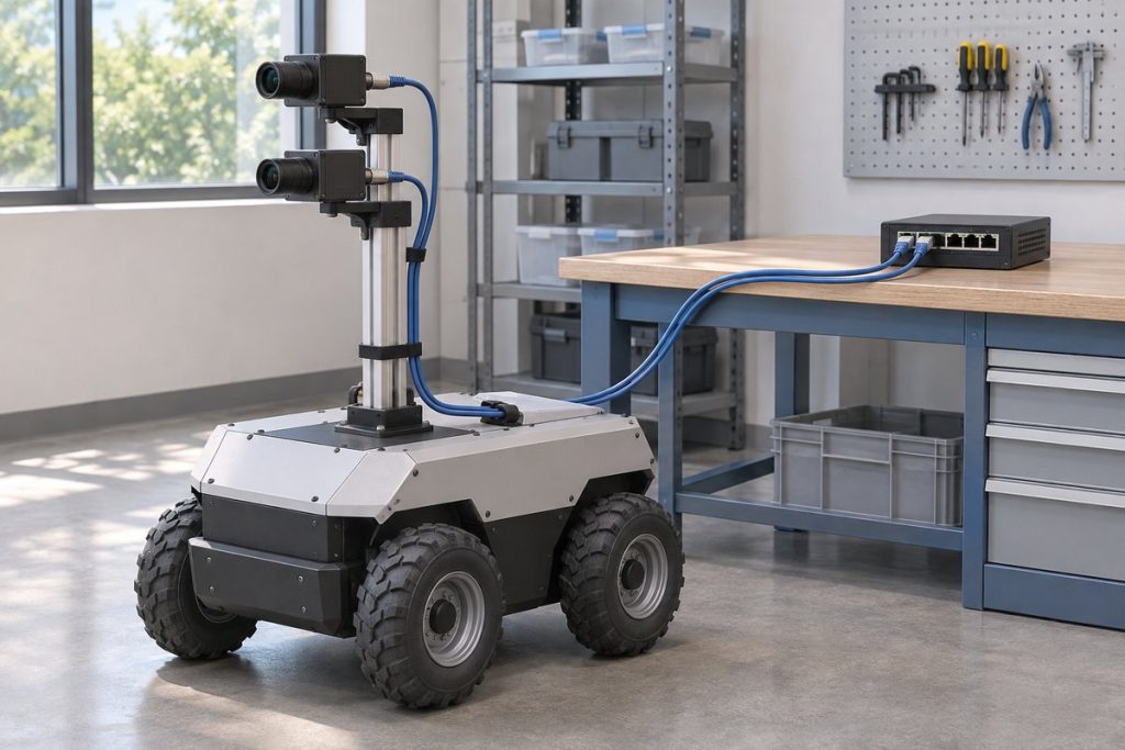
If an Ethernet camera responds to discovery but delivers no usable images, check packet-size compatibility along the complete path before changing your perception software. If one camera works but several fail together, test simultaneous bursts separately from average bandwidth. Start with a supported standard-size configuration, establish a repeatable baseline, then change one setting at a time. A larger MTU is worth keeping only when the installed robot delivers complete, timely frames under its actual workload.
This evaluation is for robot-side image transport. It does not establish camera-driver compatibility, synchronization accuracy or robot safety. Keep the robot stationary during network experiments and use the camera supplier’s instructions for your exact hardware and software combination.
A successful ping does not qualify the image path
Discovery, configuration and image transfer exercise different traffic sizes. Carnegie Robotics documents a useful diagnostic pattern for MultiSense: small control exchanges may succeed while image delivery fails because the host cannot receive the camera’s configured packet size. Its network setup documentation explains the independent camera and host MTU settings. Treat that as a reason to inspect the path, rather than proof that every camera with missing images has the same fault.
Begin by separating three observations: whether the device is reachable, whether the acquisition software receives complete frames, and whether the application consumes those frames before its deadline. A working control connection answers only the first question. A display that updates occasionally does not answer the other two. Preserve the original configuration and error counters before making changes so that a later improvement can be traced to a specific action.
Write down the path before raising packet size
Draw the camera, every switch or adapter, the selected host interface and the receiving application. Include shared uplinks and any service laptop connection that changes the topology. Record camera firmware, host driver, sensor SDK, interface identity, negotiated link rate and the configuration that survives a restart. Use the exact network segment carrying images; a management connection on another interface can conceal a problem.
For each camera, your worksheet should record the configured packet-size parameter, its documented units, supported range and current value. Beside each intermediate device, record its documented frame-size limit and the setting actually applied. Camera packet size, IP MTU and a switch’s maximum Ethernet frame size may use different accounting conventions. Check the respective manuals before comparing numbers or treating identically named options as equivalent.
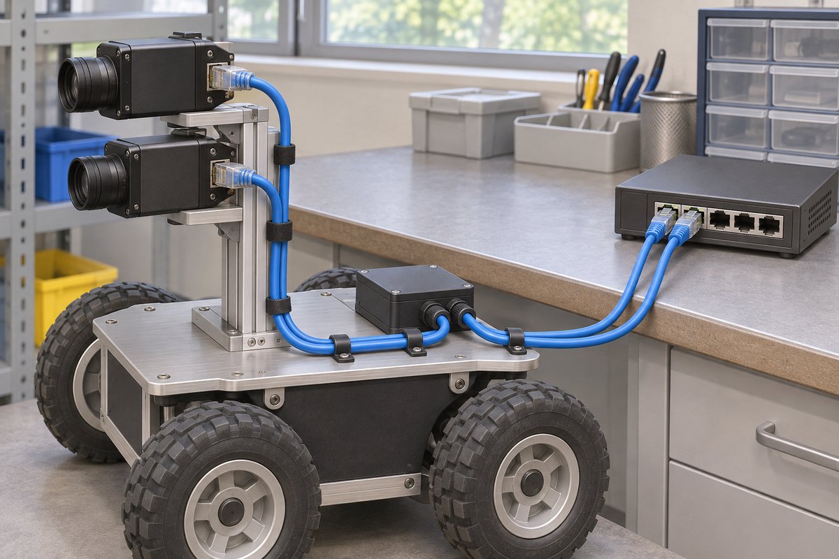
A minimal direct connection can help isolate a suspect switch or adapter, provided the camera’s power and connection requirements allow it. Carnegie Robotics recommends minimizing intervening devices for its sensors and warns that adapter capabilities vary. Do not assume that an adapter capable of negotiating a link also supports the packet size you intend to use.
Separate packet-size failures from synchronized bursts
Basler describes simultaneous multi-camera acquisition as a situation where incoming bursts can temporarily fill switch or NIC buffers. Its lost-packet troubleshooting guide recommends a 1500-byte starting configuration and discusses inter-packet and frame-transmission delays. Those controls are camera-specific; confirm their availability and units in your own SDK.
Run the following sequence at a documented resolution, pixel format and trigger pattern. Set pass limits before collecting results: required complete-frame rate, permitted loss, maximum application frame age and observation duration. There is no universal acceptable value for these limits. A slow inspection snapshot and a moving perception pipeline can require different criteria.
| Stage | Change under test | Evidence to retain | Decision |
|---|---|---|---|
| Single-camera baseline | Supported standard packet size; minimal path | Complete frames, device/host errors, acquisition settings | Resolve basic acquisition failures before adding cameras |
| Installed path | Add the actual switches and adapters | Same counters and workload, topology revision | Investigate a regression at the inserted boundary |
| Concurrent cameras | Activate the production trigger pattern | Per-camera loss, resends where exposed, frame age | Distinguish burst contention from individual-path failure |
| One tuning change | Trial a supported packet size or transmission delay | Before/after settings and equivalent captures | Keep only a repeatable improvement within deadlines |
| Installed workload | Add inference, recording and expected network traffic | Frame completion, application age, host load | Accept the concurrent system rather than an idle receiver |
| Restart and restore | Restart using the deployment procedure | Read-back settings and repeated acceptance result | Reject configurations that cannot be reproduced |
Choose the change that matches the symptom
If standard-size images work and larger packets do not, revisit path support and configuration before adjusting buffering. If individual streams work but synchronous acquisition fails, examine burst timing and shared resources. If complete frames arrive but perception uses stale data, follow the application queue and processing path; transport tuning alone cannot demonstrate that the perception deadline is met.
Increasing inter-packet delay spreads transmission over time, but it can reduce achievable frame rate. Staggering transmission starts may reduce simultaneous pressure while changing when each frame arrives. Compare both effects against the application’s timing requirement. Do not equate aligned exposure with simultaneous image arrival, or claim that transport settings establish sensor synchronization.
Stop a tuning trial when it fails the agreed frame-rate or age limit, even if a packet-loss counter improves. Retain a known working configuration and document how to restore it. Record unexplained losses as unresolved rather than hiding them inside an average throughput figure.
Turn the results into a computer-evaluation brief
The sensor-fusion architecture guide provides the wider context for connecting sensor transport to robot-side processing. Once your network requirements are explicit, the MScape N210 evaluation path is a relevant place to discuss the onboard computer. This checklist makes no claim that a particular camera, jumbo-frame setting, switch or SDK is supported on that computer.
If the workload needs a supplier-certified camera stack or a specific network feature, request evidence for the exact configuration before selecting hardware. An Ethernet connector alone does not establish either requirement. Where the path cannot support larger packets, retain a supported size and reconsider stream rate, pixel format or topology against the image-quality and timing requirements.
Send your sensor-network evaluation brief with robot type, camera count and modes, topology, trigger pattern, sensor stack, control bus, compute target, power budget, environment and deployment timeline. Include quantities, delivery country and the acceptance record so the discussion can focus on configuration evidence and the remaining integration work.