English
 Español
 Português
 Deutsch
 한국어
한국어 日本語
日本語 Italiano
 Français
 العربية
 Türkçe
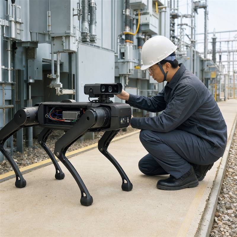
A quadruped robot edge AI computer should be selected around the robot鈥檚 sensor paths, local perception workload, communications, packaging, and validation plan鈥攏ot just a headline compute number. For inspection missions, the practical job is to keep perception and decision-support workloads close to the moving machine while preserving clear boundaries with the robot鈥檚 dedicated motion and safety functions.
Short answer
A quadruped robot edge AI computer is robot-side hardware that receives camera and sensor data, runs local AI and perception workloads, exchanges information with the rest of the robot, and fits the power, thermal, and mechanical constraints of a mobile body. It is not automatically the robot鈥檚 motion controller. Start by mapping each signal and workload, then validate the full sensor-to-decision path on the actual robot.
Why quadruped inspection changes the compute question
Legged inspection robots are often evaluated in places where floor conditions, lighting, connectivity, and sensor placement vary: utility corridors, plants, tunnels, outdoor assets, and maintenance areas. A bench demo can look convincing with one camera and a stable network, then become difficult to reproduce after the robot gains depth sensing, thermal inspection, lidar, an IMU, remote diagnostics, and a constrained enclosure.
The engineering question is therefore not 鈥淐an this computer run a model?鈥?It is 鈥淐an the robot keep the right sensor data, inference path, interfaces, and physical integration together through the mission?鈥?The live MScape site presents quadruped robots among its broader robotics application categories on the application cases page; that is a useful starting point for an architecture discussion, not proof of a one-size-fits-all configuration.
Separate perception compute from motion and safety responsibilities
A quadruped needs several layers of computing and electronics. Their boundaries should be explicit before model selection. The edge AI computer may support vision, sensor processing, mapping inputs, mission logic, local inference, logging, and communications. A dedicated robot control system remains responsible for low-level actuation and safety functions defined by the robot design. Keeping that separation clear prevents an AI-compute selection from becoming an unsupported control-system claim.
| Layer | Typical responsibility | What to validate |
|---|---|---|
| Sensor acquisition | Cameras, depth, thermal, lidar, IMU, and robot-state signals | Interface fit, connector retention, timestamp handling, cable routing, and service access |
| Robot-side edge AI | Perception, model inference, sensor fusion inputs, mission-level decision support, and data handling | Workload fit, memory headroom, thermal behavior, recovery after power events, and communications |
| Dedicated robot control and safety | Actuation, low-level closed-loop functions, and machine-specific safety design | Clear interfaces and failure behavior; do not assume these roles move into the edge AI computer |
| Remote systems | Fleet supervision, reports, data retention, and heavier offline analysis | What must continue locally when coverage is intermittent |
Build the sensor-to-decision map first
Write a one-page map before comparing hardware. List every sensor, its interface, expected data owner, processing stage, and what happens if it is missing. Then list the local workloads: obstacle and terrain perception, thermal anomaly screening, visual inspection, localization inputs, mission monitoring, or recording. This exposes whether the limiting factor is compute, camera connectivity, storage, power conversion, heat removal, or enclosure space.
A practical inspection scenario
Consider a quadruped that patrols an industrial corridor. Forward and side cameras help with route awareness; a thermal camera supports asset inspection; an IMU and robot-state data add context. The robot-side computer can organize incoming data and run the selected perception and inspection workloads locally. It can pass high-level outputs to the rest of the architecture, while fleet reporting and review remain remote. If connectivity drops, the team must decide in advance which functions continue, which data are buffered, and which mission actions require a safe stop or handoff.
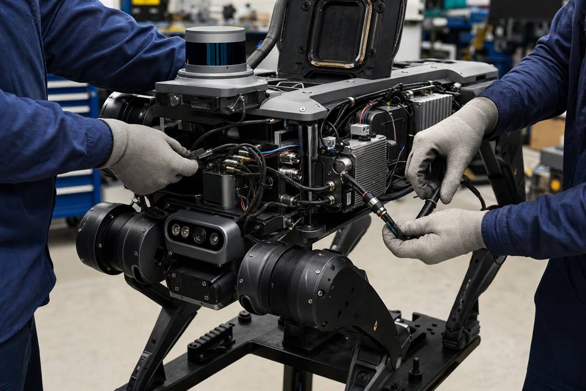
A useful validation scene: make the physical sensor, power, cable, and service path visible before treating AI throughput as the only decision.
Common integration failures鈥攁nd the earlier checks that catch them
| Failure mode | Why it appears late | Early check |
|---|---|---|
| Camera plan expands after the enclosure is fixed | A prototype uses fewer sensors than the field robot | Reserve interface, harness, and mounting paths for the intended sensor roadmap |
| Inference works on a bench but not through a mission | Power, heat, motion, cable strain, and logging were not exercised together | Run a representative mission with the enclosure closed and all required workloads active |
| Remote connectivity hides local design gaps | Cloud or nearby infrastructure carried an unplanned part of the workflow | Test the defined local behavior during a controlled connectivity interruption |
| Edge AI and robot control responsibilities are blurred | Teams use broad labels instead of an interface map | Document the data exchange, authority, and fault response for every subsystem |
Where N203 and N210 fit in a quadruped evaluation
Once the engineering map is clear, MScape N Series hardware can be considered as a robot-side compute path. The MScape N203 multi-camera edge AI computer is the relevant starting point when camera-rich perception and related interface planning drive the architecture. The MScape N210 robotics edge AI computer is a relevant path when sensor fusion and industrial interconnect are central to the robot-side design. Evaluate both against the actual sensor map, software stack, enclosure, and power/thermal constraints; neither should be chosen solely because it is associated with quadruped robots.
If the immediate question is specifically camera interface planning, see the related guide, N203 for camera-rich robots: GMSL2 perception and robot-side AI compute. For a broader model-selection process, start at the N Series product overview.
Five-step validation sequence
- Freeze a representative sensor and workload map, including a future-growth assumption.
- Prove interfaces and time relationships with the intended cameras, sensors, and robot-state feeds.
- Run local workloads under realistic power, temperature, vibration, and cable-routing conditions.
- Exercise defined degraded cases: a missing sensor, a recoverable power event, and intermittent connectivity.
- Review the evidence with robotics, software, mechanical, and procurement stakeholders before the design is released.
FAQ
Does a quadruped robot edge AI computer replace the robot controller?
No. An edge AI computer can support local perception, inference, communication, and action-oriented workloads, but that does not make it a motion or safety controller. Assign responsibilities from the actual robot architecture.
Should all quadruped AI run on the robot?
Not necessarily. Keep workloads local when the mission, connectivity, data path, or response needs require it; use remote systems for suitable reporting, storage, and offline analysis. Define the boundary before hardware selection.
What should a supplier review include?
Share robot type, camera count and interfaces, sensor stack, control-bus boundary, target workloads, power and thermal envelope, enclosure constraints, validation plan, and deployment timeline.
Turn the quadruped architecture into an engineering review
Preparing a quadruped inspection project? Contact MScape with the robot type, camera count, sensor stack, control-bus boundary, target compute workload, power budget, enclosure limits, and deployment timeline. That gives the engineering conversation a concrete starting point.