English
 Español
 Português
 Deutsch
 한국어
한국어 日本語
日本語 Italiano
 Français
 العربية
 Türkçe
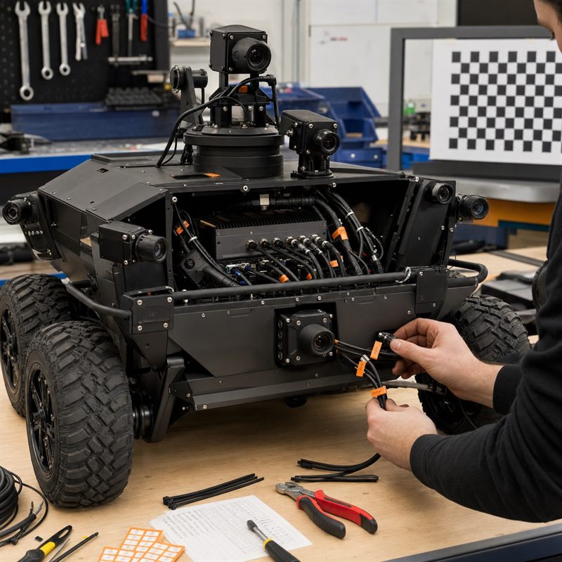
A GMSL2 camera interface does not, by itself, confirm that a camera will work with a Jetson computer. Before selecting hardware, identify the camera and serializer, the receiving hardware, cable and power arrangement, and the supported driver package. Then validate the exact combination at the required resolution, frame rate and synchronisation conditions. This guide provides a compatibility worksheet and a staged test plan for evaluating a multi-camera system, including the MScape N203.
Confirm a complete camera chain, not just a connector
NVIDIA’s Jetson Linux r36.4.4 GMSL framework guide describes a specific reference setup, including sensor, serializer and deserializer drivers. It also explains virtual-channel configuration between the deserializer and Jetson receiver. That reference is useful for understanding integration dependencies; it is not an N203 compatibility list or proof that another camera module works unchanged.
Ask the camera vendor and computer supplier to confirm the same bill of materials and software baseline. Record unverified combinations as unverified, even if the connector fits or an individual component appears in a reference design.
Use this compatibility worksheet before ordering
| Item | Record for your system | Evidence to request |
|---|---|---|
| Camera | Vendor, full part number, sensor, hardware revision and lens | Camera datasheet and supported operating modes |
| SerDes chain | Camera-side serializer and computer-side receiving configuration | Supplier confirmation for this pairing, including required firmware or configuration |
| Cable and power | Connector pinout, cable type and length, power source and grounding | Approved wiring and power specification; confirm whether power over coax is supported, required or prohibited |
| Software baseline | JetPack / Jetson Linux release, kernel, board image and driver package | Matched installation instructions, package version and supported upgrade path |
| Capture modes | Resolution, frame rate, pixel format, bit depth and processing path | Evidence for the requested combination, not just a camera’s maximum specification |
| Multiple streams | Camera-to-port mapping and simultaneous stream configuration | Validated multi-camera configuration and stable device identification |
| Synchronisation | Required timing relationship, trigger method and acceptable skew | Documented implementation and measurement method; timestamps alone do not establish simultaneous exposure |
| Recovery | Response to missing frames, restart and an unavailable camera | Supported recovery procedure and application-visible error reporting |
Give each row an owner, confirmation date and status: confirmed, pending or rejected. A pending item that determines whether the system can function should remain an open selection risk, not become an assumed feature in the purchase specification.
What the N203 specification establishes
The MScape Product Brochure 2026.7.V2 lists the N203 multi-camera edge AI computer with NVIDIA Jetson AGX Orin 32 GB or 64 GB options and 8 × GMSL2. These facts make it a candidate for a camera-rich robotics design. They do not establish eight simultaneous streams at every resolution, a guaranteed application frame rate, synchronisation accuracy or compatibility with any particular camera.
Before selecting N203, obtain confirmation for the camera part numbers, cable and power arrangement, software image and simultaneous modes in your worksheet. Do not infer support for hot-plugging, power over coax or a specific SerDes component from the interface count. If a required camera combination remains unverified, resolve that dependency before treating the hardware selection as complete.
Estimate the pixel load, then measure the application
Illustrative calculation, not an N203 benchmark: assume four cameras each produce 1920 × 1080 pixels at 30 frames per second using packed 12-bit pixels.
Per-camera pixel payload = 1920 × 1080 × 30 × 12 = 746,496,000 bits/s, or approximately 0.746 Gbit/s. Four such streams total approximately 2.986 Gbit/s of pixel payload.
This excludes blanking, transport overhead, metadata and other implementation details. Unpacked memory buffers, colour conversion, copies, recording and inference can impose different loads. The total above is not a prediction of how traffic is divided across physical links, and it cannot establish capture support or application performance.
Use the estimate to ask more precise questions. Which requested capture modes are supported together? What buffers and conversions does the application use? What recording rate is required? Then measure frame delivery and end-to-end processing delay with the intended software and cooling arrangement.
Validate in stages and keep the evidence
Set project-specific pass limits before testing, including duration, allowed frame loss, timing error and recovery time. The stages below are a suggested engineering workflow, not completed MScape test results.
| Stage | Test scope | Evidence to retain |
|---|---|---|
| 1. One camera | Bring up a supplier-confirmed camera with the specified image and driver | Part numbers, versions, capture settings and successful frame output |
| 2. Intended camera count | Capture every required stream concurrently before adding inference | Port mapping, frame counters, timestamps and driver errors |
| 3. Timing requirement | Measure the required relationship between camera exposures or outputs with an appropriate test method | Method, measured skew and comparison with the agreed limit |
| 4. Full application | Run capture, processing, inference, recording and communication together | Dropped frames, processing delay, memory use, temperatures and throttling |
| 5. Fault and restart | Use supplier-approved fault simulations and restart sequences; do not assume live cable removal is permitted | Detection, degraded behaviour and repeatable recovery |
| 6. Configuration freeze | Repeat the accepted workflow using the release image and final installation | Image identifier, settings, wiring, results and unresolved limitations |
Keep camera-specific results with the broader robotics interface-validation record. When a driver, camera revision or system image changes, use the affected dependencies to decide which checks need repeating. An earlier result remains evidence for its recorded configuration, not automatic approval of a new one.
Request an N203 camera-compatibility review
Send the camera part numbers, quantity, capture modes, synchronisation requirement, cable lengths, software versions, workload, power and environment constraints, project quantity and delivery country through the MScape inquiry page. Include the unresolved rows from your worksheet so the discussion can focus on specific integration dependencies.
MScape N Series products are not available for delivery to the United States or Canada.