English
 Español
 Português
 Deutsch
 한국어
한국어 日本語
日本語 Italiano
 Français
 العربية
 Türkçe
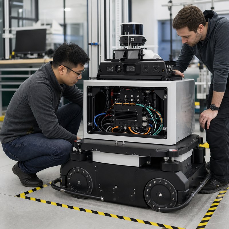
Draw the architecture before selecting hardware
A sensor fusion system combines observations that have different rates, timestamps, fields of view, noise, and failure modes. The edge computer must receive the data, preserve enough timing information to correlate it, run the required workloads, and expose a result the robot can use. It must also record enough evidence to diagnose a bad result.
| Layer | Questions | Evidence |
|---|---|---|
| Acquisition | Which cameras, lidar, radar, IMU, GNSS, encoders, and machine networks connect physically? | Model numbers, protocol, connector, cable, driver, rate, resolution, payload. |
| Time | Where are timestamps created? Which clock is authoritative? What offset and drift are acceptable? | Clock diagram, synchronization method, measured offset/drift, late-data policy. |
| Processing | Which streams are decoded, fused, inferred, recorded, or forwarded concurrently? | Pipeline graph, queue limits, CPU/GPU/memory profile, drop counters. |
| Robot handoff | What result is sent to planning or control? How are confidence, stale data, and exceptions represented? | Message definition, sequence/timestamp fields, timeout and degraded-mode test. |
Use a sensor and bandwidth worksheet
For each stream, record the nominal and peak payload rather than relying on interface labels. For an uncompressed image, a planning estimate is:
payload per second = width x height x bytes per pixel x frames per second
This estimate excludes packet, transport, encoding, buffering, and protocol overhead. Use measured traffic for the final design. Keep separate totals for each physical link, the memory and processing pipeline, and local storage. A group of interfaces may be electrically available while the complete concurrent data path still needs validation.
| Worksheet field | Example entry format | Acceptance question |
|---|---|---|
| Camera | Model / GMSL2 / 1920×1080 / 30 fps / RAW or encoded / cable length | Does the exact camera, serializer, cable, and driver work in the planned topology? |
| Lidar | Model / Ethernet / packets per second / timestamp source | Are loss, reordering, and clock alignment visible in logs? |
| IMU or GNSS | Protocol / update rate / timestamp source / expected drift | Can the pipeline identify stale or misaligned samples? |
| Vehicle data | CAN FD bitrate / message IDs / update rates / bus owner | Are load, error counters, and timeout behavior tested? |
| Recording | Streams retained / format / hours / overwrite policy | Does storage keep up during the full AI workload? |
Define synchronization and stale-data behavior
“Synchronized” is incomplete without a tolerance and a measurement method. Define the maximum allowed timestamp difference for the fusion algorithm, the clock source, where timestamps enter the data path, and what happens when a sample arrives late. Record both offset and drift over the intended run time.
Worked example: an autonomous material-handling robot
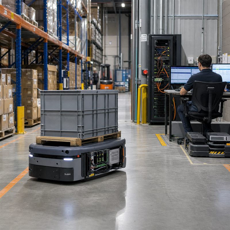
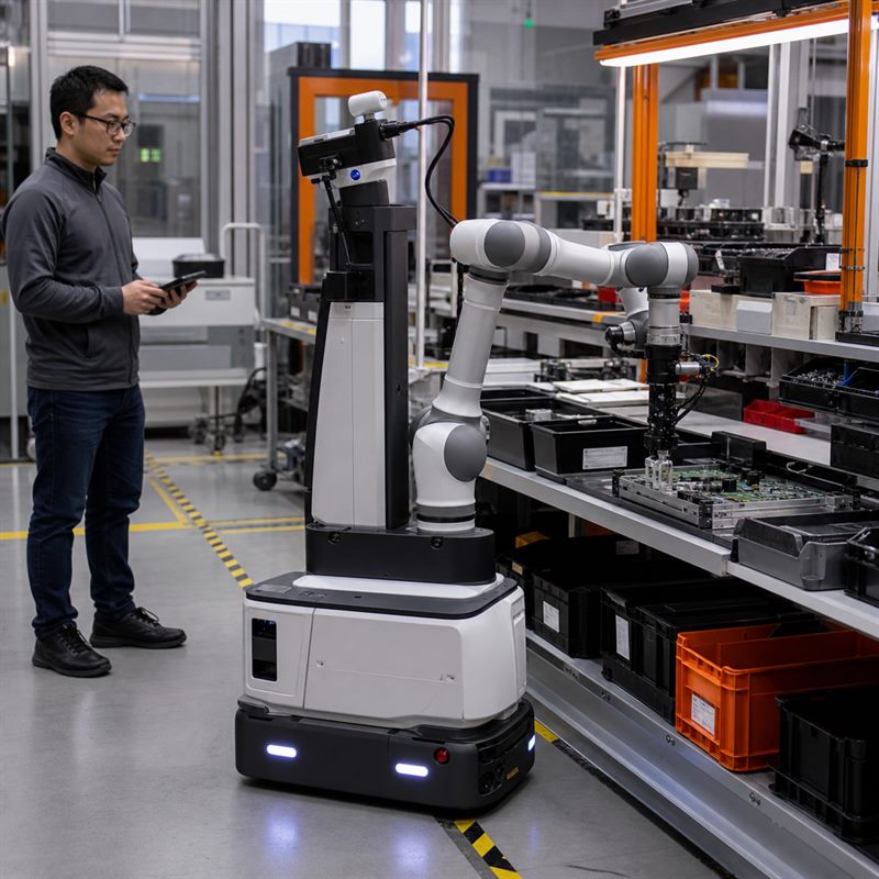
Assume a robot uses six GMSL2 cameras, one Ethernet lidar, an IMU, and CAN FD vehicle data. It runs camera preprocessing, detection, localization support, logging, and a ROS 2 application concurrently. The selection sequence is:
- Confirm the six exact camera models, serializers, cables, and driver versions.
- Map the lidar and service network to separate or shared Ethernet paths and measure peak traffic.
- Define the common clock and the maximum time difference accepted by the fusion pipeline.
- List CAN FD messages, rates, ownership, and behavior when vehicle data is late.
- Measure the full workload while recording data and after the system reaches thermal steady state.
- Interrupt one approved input and verify stale-data detection, degraded behavior, logs, and recovery.
This architecture makes N203 and N210 plausible candidates because both list AGX Orin options and eight GMSL2 inputs. The physical connection design decides which is more suitable: N203 lists enclosure-mounted Ethernet and USB interfaces, while N210 lists four Gigabit Ethernet and six USB 3.0 connections through an automotive-style expansion harness, plus pin-header connections. Review the mechanical and harness drawings before making the choice.
Current N210 facts to verify against the project
The 2026.7.V2 brochure lists the following N210 configuration. These are product specifications, not measured application results or guarantees of sensor compatibility.
| Item | Brochure specification | Project check |
|---|---|---|
| Compute module | NVIDIA Jetson AGX Orin 32GB or 64GB; listed 200 or 275 TOPS | Benchmark the actual models, precision, runtime, and concurrent services. |
| Camera inputs | 8 x GMSL2 | Confirm camera, serializer, cable, synchronization, and driver compatibility. |
| Expansion harness | 4 x Gigabit Ethernet with EtherCAT master support; 6 x USB 3.0 | Confirm harness drawing, terminations, lengths, bandwidth, master software, and licensing. |
| Additional connections | 1 x Gigabit Ethernet pin header; 2 x USB 2.0 pin header; 2 x CAN FD; GPIO, serial, I2C, SPI | Map voltage levels, connectors, bus load, and cable routing. |
| Power and mechanics | DC 9-60 V; 118 x 126 x 46 mm; 0.75 kg | Confirm supply transients, connector, clearance, cooling, and installed mass. |
| Listed software | JetPack 6.2.1, ROS 2 DDS, Linux RT, Xenomai | Confirm the delivered image and versions required by the application. |
Validation test plan
- Freeze configuration: hardware, module memory, storage, firmware, OS, drivers, sensor models, cables, and software commits.
- Prove each physical path: validate signal, driver, timestamp, rate, and error counters for every sensor.
- Run all paths together: include inference, ROS 2 traffic, recording, remote diagnostics, and other production services.
- Measure timing and loss: collect latency distributions, inter-sensor offset, drift, dropped/late samples, queue depth, and deadline misses.
- Reach thermal steady state: record temperature, clocks, throttling state, power mode, and errors in the intended enclosure.
- Exercise recovery: use approved disconnect/restart cases and verify stale-data handling, service recovery, and retained diagnostics.
Pass/fail record
Keep one row per test with: test ID; requirement; threshold; configuration ID; duration; sample count; measured result; drop/late/error count; temperature and throttling state; pass/fail; raw log location; deviation; owner; and next action. This turns a supplier discussion into a reviewable engineering decision.
FAQ
Does eight GMSL2 inputs mean any eight cameras will work?
No. Confirm the exact cameras, serializers, cables, drivers, synchronization, bandwidth, and concurrent workload.
Does N210 replace the robot controller?
No. It can support sensor processing, AI workloads, logging, and communications. Motion, drive, and safety responsibilities must be assigned separately by the robot architecture.
When should I choose N203 instead?
Compare N203 when the eight-camera requirement remains but its enclosure-mounted Ethernet/USB layout is easier to install than N210’s expansion-harness arrangement. Validate both against the same sensor and workload package.
For the wider shortlist, see the N Series overview and the interface validation guide.
Send the sensor worksheet, synchronization target, software workload, interface map, power and enclosure limits, quantity, delivery country, and schedule through the MScape inquiry page.