English
 Español
 Português
 Deutsch
 한국어
 日本語
 Italiano
 Français
 العربية
 Türkçe

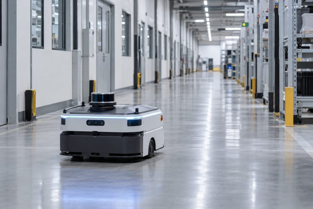
Your mobile robot seems to drift toward the left-hand shelf, even though the route on the screen is straight. Is the position estimate wrong, is the planned path wrong, or is the vehicle failing to follow a correct path? Those are different failures, and changing a localization parameter before separating them can make the next run harder to diagnose.
Start with three records from the same trip: the robot’s estimated pose, the path sent to the controller, and an independent observation of where the vehicle actually travelled. Compare them at known checkpoints. A slowly growing odometry error, a sudden jump in the map frame, and a tracking error under load leave different traces. The goal of mobile robot localization drift troubleshooting is to identify which trace changed before you tune the system.
Know which position you are looking at
Wheel encoders estimate motion from wheel rotation. An IMU adds information about rotation and acceleration. A lidar or camera can compare the current scene with a map. Each source has a different failure mode: slipping wheels make distance estimates drift, an obscured corridor may confuse environmental matching, and a stale sensor message can make a good observation arrive too late to help.
In a ROS 2 Nav2-style system, the transforms commonly connect map to odom, odom to base_link, and the robot body to its sensor frames. The Nav2 transform guide explains those relationships and notes that mapping or localization normally supplies the live map-to-odom transform, while the odometry system supplies odom-to-base_link. Do not treat every pose displayed in a user interface as the same measurement.
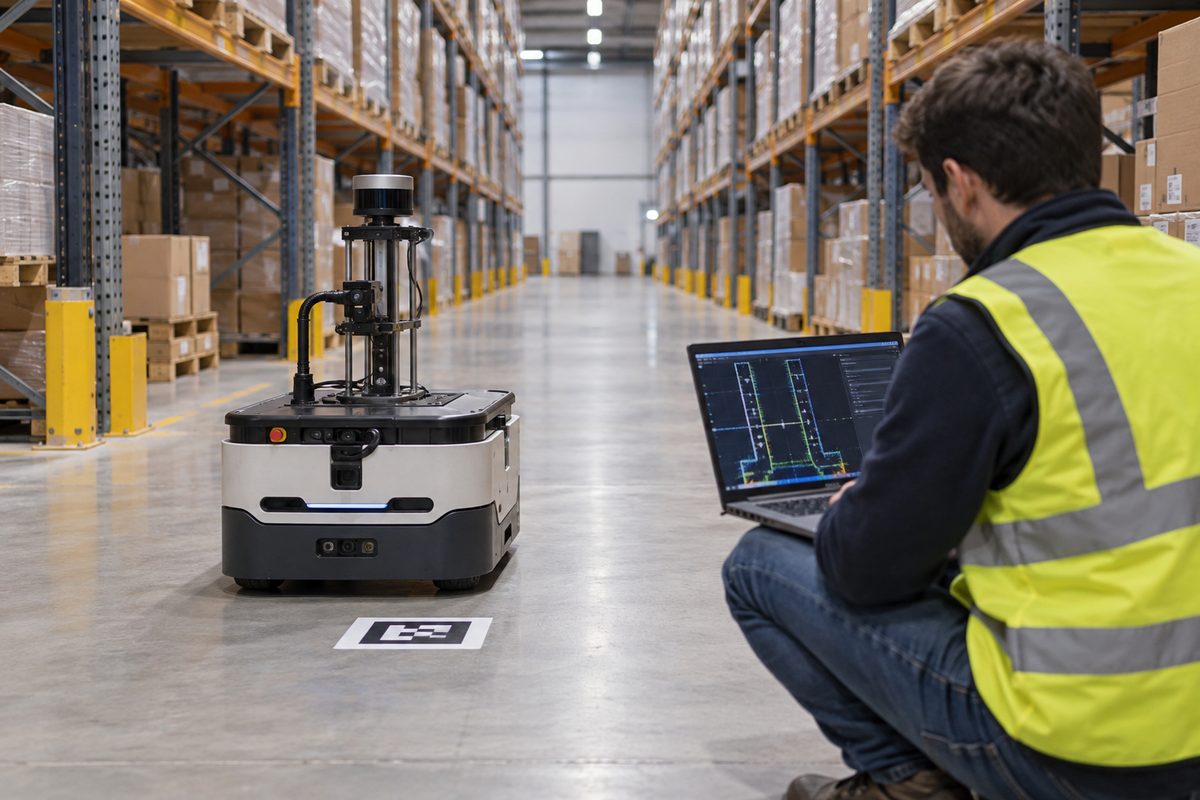
For a test run, save both the odometry-frame and map-frame trajectory, the planner’s path, control feedback, sensor timestamps and the map version. Add a few external checkpoints that can be measured independently of the robot’s own estimate. A floor marker is useful as a repeatable reference, but the marker and the measurement method also have uncertainty. State how you located the robot relative to it.
Read the shape of the error before changing a parameter
| What you see | Likely boundary to inspect | Evidence to save |
|---|---|---|
| Error grows gradually with distance | Wheel scale, wheelbase, slip or odometry fusion | Encoder and IMU data, odom trajectory, surface and payload |
| Map position jumps in a similar aisle | Environmental matching or initialization | Raw scan or image, map, candidate pose and localization state |
| Estimated pose is stable but the vehicle misses the path | Controller tracking or physical motion | Commanded path, wheel feedback and independently observed position |
| Failure appears after sensor service | Timestamp or sensor-to-body transform | Mounting record, calibration version and message age |
These are investigation paths, not diagnoses from a single symptom. More than one can occur together. A worn wheel may distort odometry while similar shelves prevent the map matcher from correcting it. Keep raw sensor messages and transform versions where possible; a smoothed final track can hide the boundary that failed.
Check accumulated odometry error on a measured route
A simple example shows why a small scale error matters. If a wheel-based estimate is 2% high over a measured 20 m route, it would overstate travel by about 0.4 m if left uncorrected. That is arithmetic for an illustrative condition, not the measured localization error of any robot. Map updates and other sensors may reduce the difference; slip during one turn may make it worse.
Run the same route at a controlled speed and payload. Compare odometry distance with an external measurement at more than one point, including the end of a turn. If the error builds smoothly, inspect wheel diameter, encoder direction, wheelbase, IMU orientation and floor friction. Repeat on the surface and with the load that caused the complaint. Tuning a map matcher to compensate for an incorrectly scaled odometry input may produce a clean-looking trace in one corridor and a new fault elsewhere.
Nav2’s robot_localization setup guide discusses combining continuous odometry sources and checking the odom-to-base_link transform. Use its configuration details in the context of the software version you actually deploy; the guide does not certify a particular robot’s calibration.
Investigate a sudden map jump separately
Repeated doors and identical rack bays can make two places look alike. The odometry path may remain smooth while the map-frame pose snaps toward another aisle. Compare the raw lidar scan or image with the map at that moment. Was the area altered by pallets, was a sensor partially blocked, or was the robot initialized at an uncertain location after someone moved it by hand?
Nav2’s AMCL configuration documentation describes the laser and motion-model parameters available to a map-based localization system. A parameter change may help a system handle a known condition, but it cannot make an outdated map depict a relocated rack. Include map revision and starting pose in every comparison. When localization confidence is not sufficient for the task, the robot’s approved operating logic must decide whether to pause, return to a known area, or request help.
Do not confuse correct localization with good path tracking
If an independent checkpoint agrees with the estimated pose but the robot cuts a corner, examine the path command, steering or wheel feedback, payload and floor conditions. The controller may not have followed a perfectly reasonable path. A camera view of the physical route and synchronized feedback can resolve that disagreement more quickly than another localization adjustment.
Timing can produce a similar complaint. Ask whether a sensor’s timestamp means capture time or host arrival time. If a pose reaches the controller 50 ms later than expected while a robot is moving at 1 m/s, the vehicle travels about 5 cm during that interval. The 5 cm is a distance travelled, not an automatic claim of 5 cm localization error; the system may compensate for motion. Compare message age and motion at the point where the pose is consumed. The sensor-fusion integration guide provides a broader worksheet for clock sources, stale inputs and concurrent sensor traffic.
Sensor mounting matters too. After a lidar bracket or camera position changes, confirm the sensor-to-body transform and its direction. A transform that was correct before service may make a straight wall appear skewed in the robot frame afterward. Keep the mounting photo, transform file and calibration date with the test record.
Use a route that exposes the failure
Choose checkpoints at the start, after a straight section, after a turn, inside a repeated aisle and at the return position. Record the estimate, planned path, physical reference, payload, speed, map version and any intervention at each checkpoint. Report the largest task-relevant deviation and the distribution across repeated runs, not only a route-wide average that can hide one dangerous narrow passage.
The onboard computer is part of this evidence path: wheel, IMU, lidar and camera data have to arrive with usable timestamps while other applications run. An MScape N201 can be considered as a local computing option when its delivered interface configuration matches the sensor plan. It does not determine the robot’s localization accuracy by itself. If you are evaluating hardware, share the sensor models, software stack, route, required pose age and recorded failure so the connection and workload can be reviewed against the actual task.