English
 Español
 Português
 Deutsch
 한국어
 日本語
 Italiano
 Français
 العربية
 Türkçe

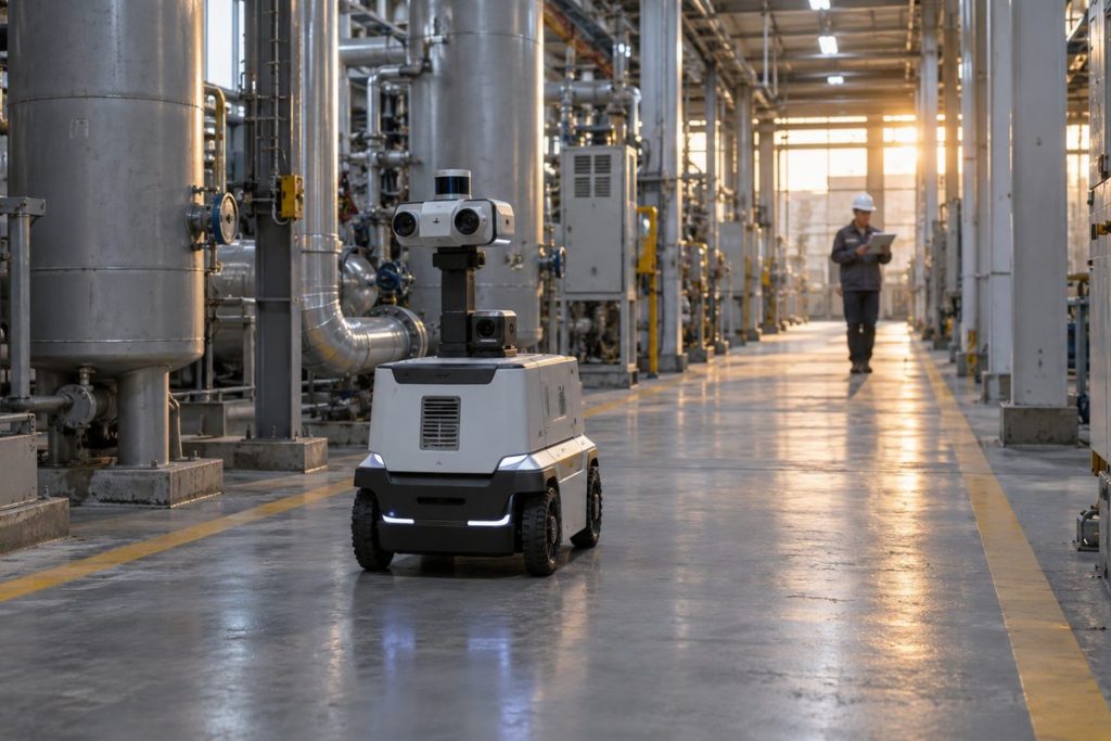
A robot can look healthy at 9 a.m. and start hesitating near the end of a shift. The camera still streams, but a perception result arrives late, a recording queue grows, or an inspection checkpoint takes longer than it did in the morning. A restart may make the symptom disappear. If your acceptance test only checks a short, idle run, you will miss the condition that matters.
For robot endurance testing, define the real duty cycle and keep task timing, temperatures, power events, memory and storage on one timeline. Set the pass and fail conditions before the run. You are trying to learn whether this particular installed robot can complete its assigned shift and recover from expected interruptions, not whether an onboard computer can stay powered for an arbitrary number of hours.
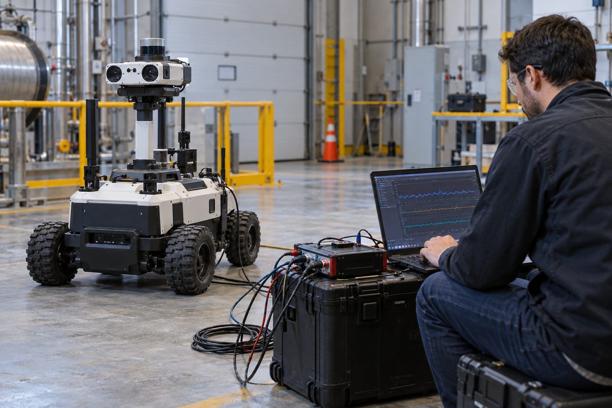
Define a shift that resembles the job
“Run it for eight hours” sounds measurable, but it leaves out the work. An inspection robot might travel for ten minutes, wait at a station, take high-resolution images, and upload evidence when a connection returns. A warehouse vehicle may spend the same time starting and stopping under load. Those two schedules stress the battery, computer and storage in different ways.
Write down the route, payload, camera modes, model version, recording policy, network conditions, charging stops and ambient range. Include a busy period, not only the easiest part of the route. If the robot normally enters an enclosed, warmer area in the afternoon, a cool open-bench test will not answer the deployment question. Keep the installed enclosure and cable routing in the record too. They affect heat removal and service access.
| Test condition | Record before the run | What a pass needs to show |
|---|---|---|
| Normal task cycle | Route, payload, sensor modes and task rate | Required tasks finish within the project’s timing and quality limits |
| Busy interval | Concurrent inference, recording and network activity | No unacceptable frame age, queue growth or missed task deadline |
| Installation | Enclosure, airflow, ambient and power mode | Stable work after the installed system reaches a representative thermal state |
| Interruption | Approved fault and expected response | Safe state, clear alert, retained evidence and controlled recovery |
The thresholds in the right column must come from the robot’s task and safety design. Do not borrow a temperature limit or recovery time from another machine. For a useful comparison, freeze the hardware, software image and mission script for each run; if you change the fan, model or route, call it a new test condition.
Put the slow frame on the same timeline as the system load
Average frame rate can hide a momentary failure. Suppose a hypothetical system processes 20 frames per second at an average age of 40 ms, but one frame every ten minutes reaches the planner 500 ms late. The mean may still look acceptable. A late frame at a narrow turn may matter far more than hundreds of on-time frames in an empty aisle. These numbers illustrate a measurement problem; they are not results from an MScape computer or a robot deployment.
Log capture time, processing completion, planner receipt and the action or inspection event that used the result. Put task phase and a shared clock reference beside those events. A dashboard with only CPU utilization cannot tell you whether a frame waited in a camera queue, inference slowed, or a write operation blocked the application. If two devices have different clocks, record how you measured offset and drift before subtracting their timestamps.
When a symptom appears, keep a short window before and after it: the raw observation or event ID, output age, queue depth, missed deadlines, frequency, temperature, input voltage, storage latency and network state. This is usually more diagnostic than a screenshot of the system after a restart. It also gives you a fair way to compare a software change against the same task.
Separate heat, power and queueing before you change hardware
If the robot becomes slower late in the run, heat is a candidate, but it is not a verdict. Compare task throughput with processor frequency, temperature and power mode. NVIDIA’s Jetson power and performance documentation describes software-visible power and thermal management. Its validation guide shows how frequencies and power modes can be observed with tegrastats. Those readings help locate a change; they do not measure the age of a robot’s planning input for you.
If clocks remain steady while frame age grows, inspect the capture and processing queues, network retry traffic and storage writes. If clocks fall while temperatures climb, repeat the same task with the installed airflow documented. If the computer resets when motors accelerate or peripherals switch on, measure voltage at the computer input rather than relying on battery state of charge. The existing installed-build thermal validation guide and power and restart guide cover those two investigations in more detail. This article connects them to a complete shift.
Battery endurance needs the same care. Dividing usable watt-hours by average watts gives a planning estimate, not evidence that the supply can handle a motor start or that the robot can still complete the route at low charge. Keep source-side voltage and current events, charging behavior and any power-protection state in the test record.
Keep enough evidence without filling the drive
Recording every image and every diagnostic topic for the whole day can create the fault you are trying to study. Continuous video, logs and backlog uploads compete with the live application for storage and network capacity. Give each class of evidence its own retention rule: low-rate health values can be kept for the full shift; task state and alerts should remain traceable; high-volume images or point clouds can use a bounded pre-event and post-event window when the project allows it.
Test the low-space case before deployment. Confirm what the recorder deletes, whether essential logs survive, and whether the live task keeps its required timing when the disk approaches the reserved-space threshold. A recorder that works on an empty drive has not passed this part of the test. Preserve the software and storage configuration with the result so a future engineer can reproduce the behavior.
Prove recovery at the task boundary
A process coming back online does not prove that the robot resumed the right mission state. After an approved power interruption or network outage, ask which checkpoint was completed, whether an alert was delivered twice, whether evidence waiting to upload remained intact, and whether the robot needs operator confirmation before moving again. A machine holding an object or entering a shared work zone may need a different restart rule from one parked at a charging station. The responsible control and safety teams define that rule.
Use a small acceptance sheet for every run: configuration ID, task version, environment, start and end time, completed cycles, timing threshold and misses, largest observed delay, resource trends, fault events, operator interventions, recovery result and raw log location. Mark the result passed, failed or inconclusive. “It ran all afternoon” is not a pass if the records cannot show which work was completed. Repeat the representative cycle; one quiet shift is weak evidence for a recurring duty cycle.
An MScape N Series onboard computer can be evaluated within this installed-system test, but the robot’s endurance and recovery depend on its sensors, power supply, software and enclosure as well. If you are preparing an evaluation, send the task cycle, connected devices, power path, enclosure, recording policy and acceptance limits. That gives the supplier a testable brief instead of a request for a computer that will simply “run all day.”