English
 Español
 Português
 Deutsch
 한국어
한국어 日本語
日本語 Italiano
 Français
 العربية
 Türkçe
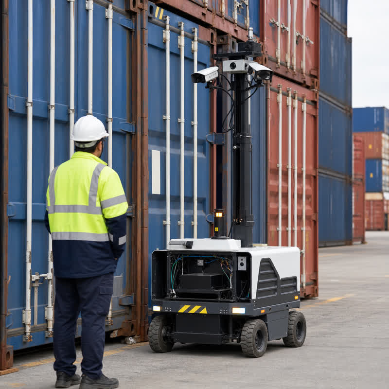
Container inspection robots need more than a camera connected to an AI workload. The robot-side computer must support the actual inspection path: image acquisition, illumination and trigger coordination, local inference or image processing, evidence capture, communications, service access, and clear boundaries to vehicle and safety functions. A useful hardware evaluation begins with that installed workflow, not with a generic compute comparison.
Short answer
An edge AI computer for a container inspection robot should be chosen by mapping every camera and sensor to the inspection decision, evidence record, physical connection, local workload, power path, enclosure constraint, and recovery action. Test the system with representative container surfaces, lighting changes, missing inputs, storage limits, and network interruptions. The computer supports perception and inspection workloads near the machine; it is not automatically the vehicle, motion, or safety controller.
Why container inspection is a workflow, not a camera-count problem
Container doors, corrugations, labels, seals, corners, and exterior surfaces create different imaging conditions. Glare, shadows, dirt, weather, camera stand-off, and vehicle position can change what a vision system receives. An engineering team may use local processing to prepare images, run a vision model, associate observations with an inspection job, and retain useful diagnostic evidence. But a convincing bench result does not prove that the deployed robot can acquire the planned views, keep cables serviceable, or recover cleanly after an interrupted job.
For this reason, define the inspection output before selecting robot-side hardware. Is the result an image record for review, a detected condition to hand to an operations system, a confidence flag that asks for another view, or input to a larger automation workflow? That question sets the camera topology, storage plan, message ownership, and validation evidence. It also prevents the edge AI computer from being assigned responsibilities that belong to a dedicated vehicle-control or safety architecture.
Build an inspection-to-evidence map first
| System area | Decision questions | Evidence to review |
|---|---|---|
| Image acquisition | Which surfaces need views? Which cameras, illumination, triggers, and mounting positions are required? | Camera map, representative image set, connection plan, calibration and cleaning procedure. |
| Local workload | What processing must stay with the robot, and what can be sent to a remote system? | Application list, representative workload test, memory and storage plan, version record. |
| Inspection evidence | How are images, timestamps, job identifiers, and diagnostic records retained and retrieved? | Data-retention rule, file naming or job-association method, retrieval and export test. |
| Interfaces | What crosses Ethernet, wireless links, or machine interfaces, and who owns each message? | Interface list, reconnect test, error reporting and service workflow. |
| Installation | Where do the computer, harnesses, power entry, and heat path sit on the robot? | Enclosure drawing, cable routing, strain relief, service-clearance and installed-workload review. |
Failure modes that expose integration risk
Deliberately testing inconvenient conditions is more useful than running only an ideal demo. The purpose is to establish how the computer, application, and wider machine architecture reveal and handle a problem.
| Test condition | What to observe | Useful outcome |
|---|---|---|
| Glare, shadow, or dirty surface | Whether the planned image path remains diagnosable and which evidence is retained for review. | The team learns whether the issue is optical, mechanical, software-related, or operational. |
| Camera or illumination input absent | Health reporting, logs, job state, and the handoff to the responsible machine function. | A missing input is visible rather than silently producing an incomplete inspection. |
| Wireless interruption | What work remains local, what is queued, and how completed evidence is reconciled. | Connectivity changes do not obscure the inspection record or diagnosis path. |
| Power cycle or storage pressure | Startup order, configuration persistence, job recovery, available storage, and technician access. | Commissioning staff can restore a known state and retrieve evidence. |
Select an N Series path after the workflow is clear
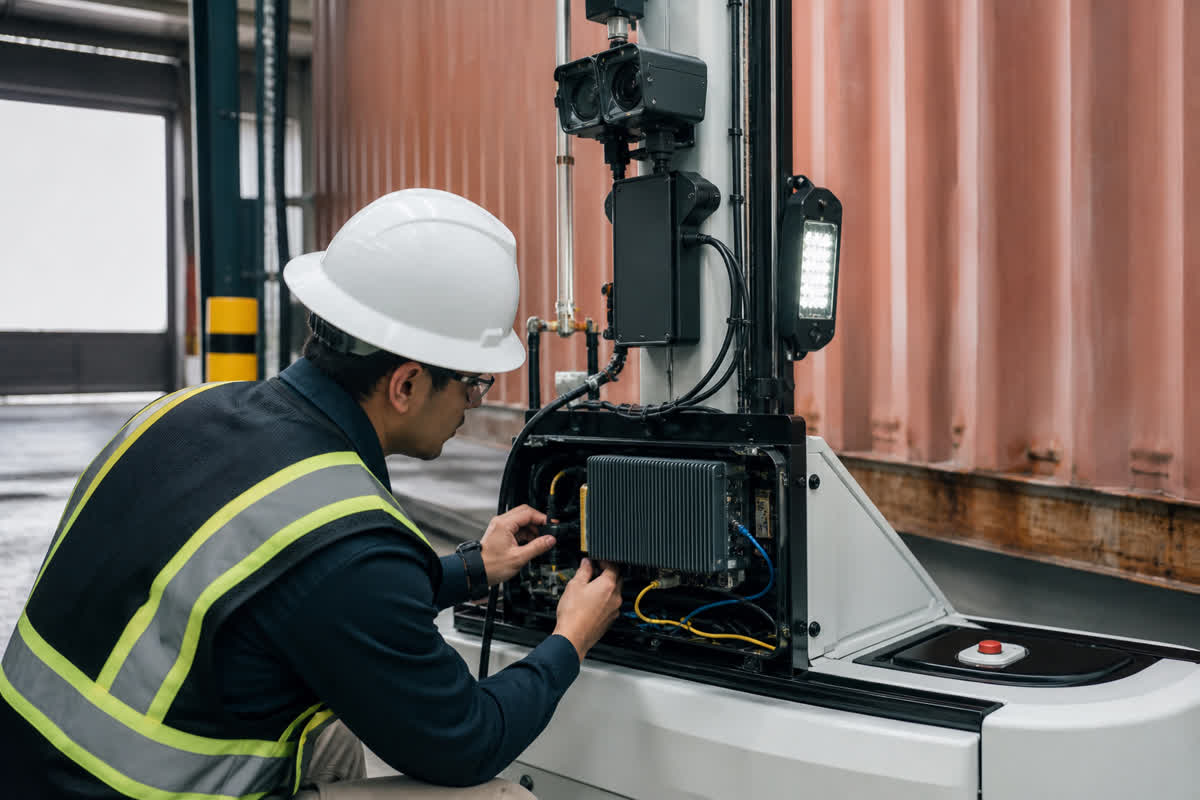
After the inspection map is defined, start with the MScape N Series product overview to frame the available NVIDIA-based robot-side computing paths. For a camera-rich inspection architecture, evaluate the MScape N203 multi-camera edge AI computer against the actual camera connection and enclosure plan. Where the robot has broader sensor, communication, and integration requirements, evaluate the MScape N210 robotics edge AI computer against the full interface map.
Neither model is automatically correct because the application is container inspection. If the local workload, installed power, package space, or software roadmap calls for a different fit, compare the intended architecture with the broader N Series options before locking a bill of materials. The robotics application cases provide useful deployment context, while the related robotics edge AI interface-validation guide helps structure an interface test plan.
A practical validation sequence
1. Capture representative inspection scenes
Collect imagery from the intended camera positions across the container conditions and work zones the application expects to encounter. Use it to test the planned acquisition, processing, and evidence workflow.
2. Fit-check the installed robot
Mount the computer and complete the intended harnessing. Review connector reach, cable protection, heat path, power entry, access for replacement, and whether a technician can inspect the system without dismantling unrelated equipment.
3. Exercise fault visibility and recovery
Disconnect a selected input, interrupt a network path, restart the unit, and approach the planned storage limit in a controlled setting. Document the health signals, logs, evidence state, and ownership of the next action.
4. Turn results into a procurement package
Record the approved configuration, interface map, installation drawing, software image, diagnostic method, test evidence, and change-control owner. This gives engineering and procurement the same reference when scaling beyond a prototype.
FAQ
Does an edge AI computer replace the robot controller?
No. It can support image processing, inference, sensor processing, communications, and evidence handling near the machine. The overall design should separately define vehicle, motion, and safety responsibilities.
Should every inspection image be processed locally?
Not necessarily. Choose workload placement based on the inspection workflow, availability needs, connectivity assumptions, evidence requirements, and what the remote system is responsible for receiving.
What should a supplier receive before recommending hardware?
Share the robot type, camera and illumination map, sensor and interface list, intended local workloads, evidence-retention needs, enclosure and power constraints, service method, and deployment timeline.
Start with the installed inspection workflow
For an N Series evaluation, contact MScape with your robot type, container views to capture, camera and sensor stack, interfaces, local workload, power and enclosure constraints, evidence requirements, and deployment timeline.