English
 Español
 Português
 Deutsch
 한국어
한국어 日本語
日本語 Italiano
 Français
 العربية
 Türkçe
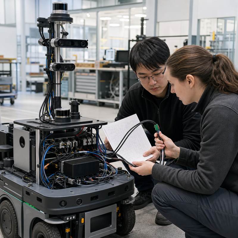
Short answer: Choose a robotics edge AI computer by mapping each robot workload to its data source, interface, failure boundary, and deployment constraint—not by starting with a headline compute figure. Camera-rich perception, sensor fusion, and higher-level planning can demand different hardware paths. A sound selection keeps the robot-side computer responsible for AI and application workloads while leaving dedicated drive, motion, and safety functions in their intended subsystems.
Robotics teams often begin with a model, accelerator, or demo and only later discover that their camera wiring, sensor timing, storage, enclosure, or recovery process determines the integration risk. Robot workload partitioning is the practical way to avoid that sequence: identify what data enters the computer, what it must produce, what happens when it is unavailable, and which subsystem owns the final action.
Start with workload boundaries, not a product shortlist
A robotics edge AI computer is complete robot-side hardware that can host perception, inference, communications, logging, and application software near the machine. It is not automatically a robot controller. A dedicated safety chain, motor drive, or low-level motion function should retain the responsibilities assigned by the robot architecture.
For selection, write one row for every workload before evaluating hardware. The useful question is not “How much compute do we need?” alone; it is “Which inputs, outputs, and recovery expectations belong together?”
| Workload group | Selection evidence to collect | Boundary to preserve |
|---|---|---|
| Perception | Camera type and count, ingestion path, synchronization needs, model runtime, storage for representative recordings. | Perception output informs the robot application; it does not replace a dedicated safety function. |
| Sensor fusion and communications | Sensor inventory, network layout, industrial communication needs, connector access, cable routing, software ownership. | Communication support can connect subsystems; it is not a claim of motion-control ownership. |
| Planning and robot application software | Concurrent processes, memory and storage behavior, update/restart path, observability, representative operating scenarios. | Higher-level decisions must still respect the robot’s separate low-level and safety architecture. |
A practical three-path selection map
After the workload map is stable, use verified N Series product pages as solution paths. The fit below is an engineering starting point, not a substitute for interface and deployment validation.
| When this is the dominant problem | Consider first | Ask before deciding |
|---|---|---|
| Multiple vision channels and a camera-led perception workflow | MScape N203 multi-camera edge AI computer | Which camera interfaces and recordings must be exercised together in the installed robot? |
| A sensor-rich robot where interconnect and software integration are central | MScape N210 robotics edge AI computer | Which sensors, networks, and application processes share the computer, and how will their connections be validated? |
| Compute-heavy perception or planning workloads need more headroom in the robot-side system | MScape N1000 high-performance robotics edge AI computer | What representative concurrent workload proves the installed thermal, power, storage, and restart behavior? |
If the robot only has a small, connected workload, do not assume that a higher-performance path is automatically the better choice. A smaller deployment may prioritize packaging, interfaces, power routing, and serviceability. Begin with the N Series robotics edge AI computer overview, then validate against the actual workload map.
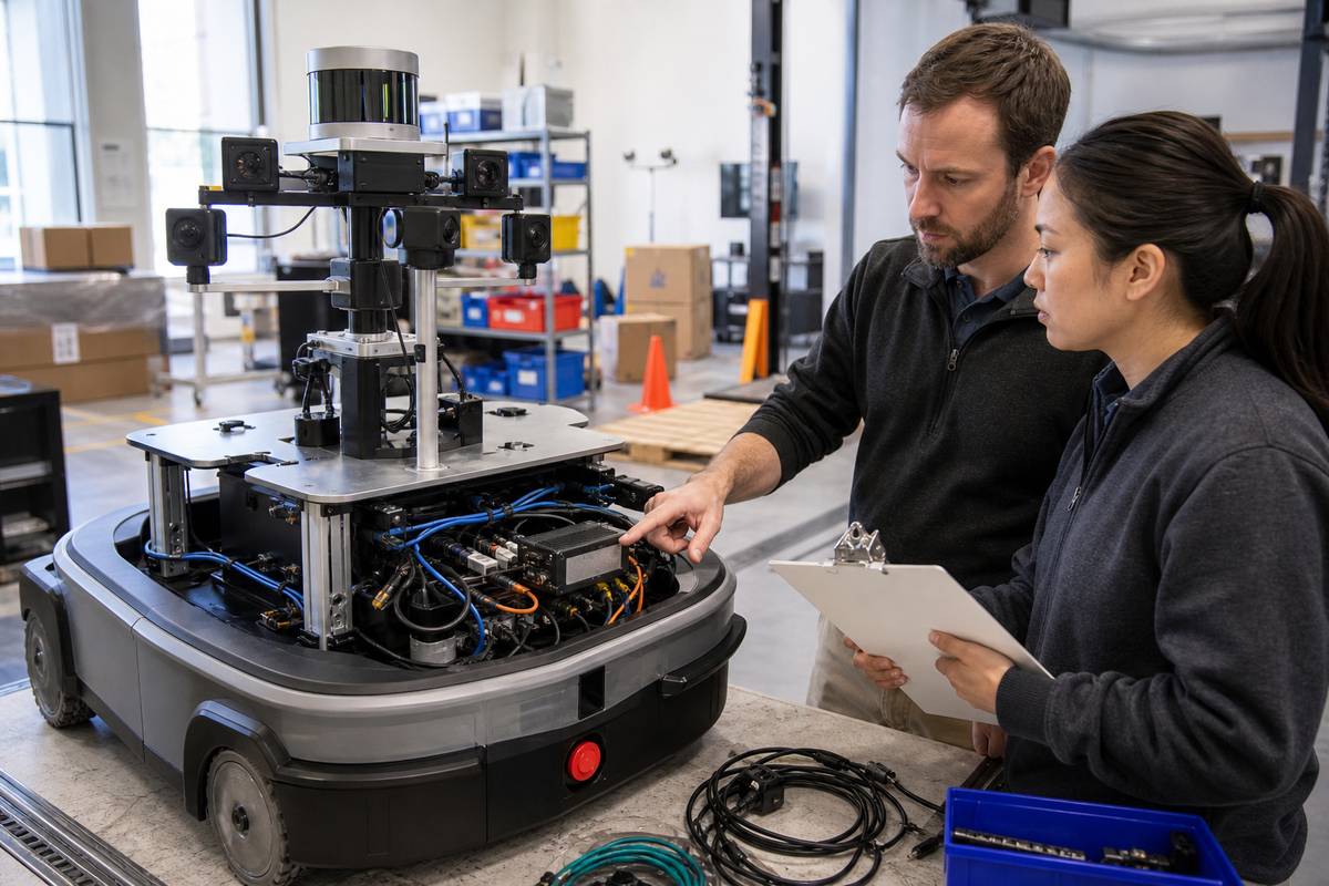
Worked scenario: a warehouse robot with cameras, lidar, and fleet connectivity
Imagine a warehouse robot that runs camera-based obstacle interpretation, lidar localization, robot application software, and fleet communications. The team first lists camera inputs, lidar and network paths, storage needed for diagnostics, and every process that restarts together. It then tests those workloads with the intended cable harness, enclosure, power arrangement, and recovery procedure.
This reveals useful decisions early. A camera-led design may need its evaluation centered on video ingestion and recording. A sensor-rich design may make interconnect and application-process ownership the larger risk. A compute-heavy stack may require a representative concurrent scenario before anyone concludes it needs a larger system. None of those findings should be inferred from a single benchmark or a polished demonstration.
Failure modes that a workload map exposes
| Weak selection habit | What it can hide | Better validation |
|---|---|---|
| Buying from compute headline alone | Input paths, memory pressure, storage behavior, and installed power or thermal constraints. | Run the representative concurrent workload on the intended robot configuration. |
| Calling every computer a controller | Unclear ownership when perception software, low-level control, and safety functions need different assurance paths. | Document which subsystem owns each action and its fallback state. |
| Testing only on a bench | Connector strain, cable routing, vibration exposure, service access, and restart recovery. | Repeat the test after installation, with the production-intent harness and enclosure. |
Validate the selection in this order
- Freeze a one-page workload map: inputs, outputs, software owners, dependencies, and fallback behavior.
- Build a representative data set and exercise the real camera, sensor, and communication paths.
- Check installed power, thermal, mounting, connectors, and service access with the robot enclosure closed.
- Test restart and recovery of the computer and application software without redefining the roles of drive or safety subsystems.
- Record the configuration, test evidence, and unresolved risks for the integration and procurement teams.
For a deeper interface-focused checklist, see Robotics Edge AI Computer Interface Validation. Relevant deployment examples are available in MScape application cases, while the About MScape page provides company context for supplier evaluation.
FAQ
Does workload partitioning mean one computer per robot function?
No. It means the team makes dependencies and ownership explicit before selecting hardware. Some functions can sensibly share robot-side computing hardware; others require a separate dedicated subsystem by design.
Is a robotics edge AI computer the same as a robot controller?
No. An edge AI computer may support perception, inference, communication, and application workloads near the machine. Its presence does not by itself make it responsible for motor, motion, or safety control.
Which N Series model should we choose?
Start with the workload map. Camera-led perception may point toward N203; a sensor-rich integration focus may point toward N210; more compute-heavy concurrent workloads may point toward N1000. Verify the final fit with the robot’s actual interfaces and installed conditions.
Send MScape your robot type, camera count, sensor stack, control bus, target AI workload, power budget, enclosure constraints, and deployment timeline through the Contact / Inquiry page. The team can help scope a verified N Series hardware evaluation path.