English
 Español
 Português
 Deutsch
 한국어
한국어 日本語
日本語 Italiano
 Français
 العربية
 Türkçe
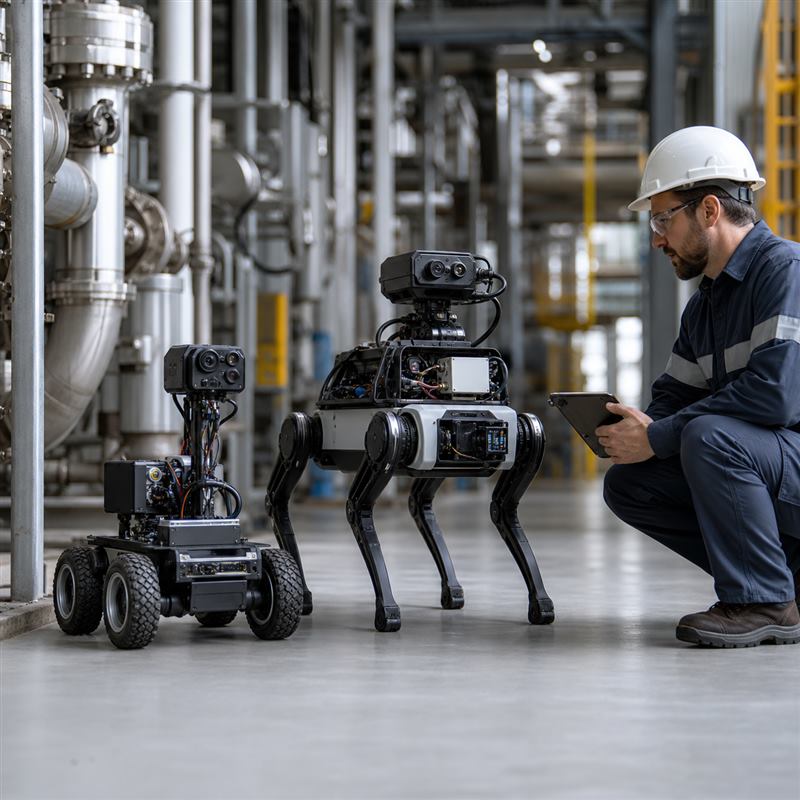
Multi-robot inspection programs often combine different machines: a ground robot for close visual checks, a quadruped for uneven areas, or a drone for elevated assets. The engineering question is not whether every workload should run in one place. It is how to assign sensing, inspection inference, mission coordination, evidence handling, and recovery work so each robot can keep operating when fleet connectivity changes.
Why multi-robot inspection changes the compute decision
One robot can be designed around one sensor stack and a single mission. A fleet adds handoffs: an aerial survey may identify a location, a ground robot may capture a closer view, and an operator may need the resulting evidence tied to the same asset and inspection pass. Treating all compute as a central service can leave an individual robot without its own perception path. Treating every decision as local can create duplicate evidence, unclear task ownership, and difficult recovery after a failed upload.
The useful boundary is functional, not marketing-led. The robot-side computer supports camera and sensor processing, local inference, communication, and action-oriented software workloads. Dedicated low-level drive, actuator, emergency, and safety functions remain with the subsystems designed for those responsibilities.
A three-layer workload map
| Layer | Good workload fit | Evidence to define before integration |
|---|---|---|
| Robot-side edge AI computer | Camera acquisition, sensor processing, local inspection inference, mission-state caching, and data packaging for upload. | Which inputs must remain usable without fleet access; where data is stored; what the robot does after a failed inference or disconnected link. |
| Fleet or site service | Task assignment, asset identity, shared maps where applicable, evidence indexing, operator review queues, and cross-robot handoffs. | A stable robot and asset identifier; upload contract; duplicate-evidence rule; operator ownership for exceptions. |
| Cloud or enterprise service | Longer-term retention, fleet reporting, model-management processes, and analysis that does not block immediate inspection behavior. | What is deferred during a connection loss, how records reconcile later, and who approves a retried or revised result. |
Start with the inspection evidence path
Before choosing a computer, follow one inspection observation from sensor to decision. For example, a quadruped observes a valve with RGB and thermal cameras. The installed computer receives the streams, runs the selected local workload, records the capture context, and queues an evidence package. A site service can then associate it with the asset record and route an exception to an operator. The exact model, runtime, and acceptance criteria should be defined by the project; do not assume an image alone is enough evidence.
This sequence also clarifies why a fleet dashboard is not a replacement for robot-side computing. The robot needs a local behavior for an unavailable service: continue an approved capture sequence, pause and preserve state, or request intervention. The right choice depends on the task and risk assessment.
Selection criteria for robot-side inspection compute
| Decision area | Question to ask | Common weak assumption |
|---|---|---|
| Sensor topology | Which cameras, depth sensors, thermal sensors, or other inputs are connected to each robot, and who owns their calibration state? | Counting sensors without mapping their physical interfaces and cable routes. |
| Workload placement | Which inference and data-preparation steps are required before a robot can make its next mission decision? | Assuming all AI work can wait for a remote service. |
| Evidence continuity | How are asset ID, robot ID, capture context, and retry status retained across a disconnection? | Uploading files without a reconciliation rule. |
| Installed constraints | How will power, thermal behavior, mounting, connector retention, and service access be checked in the real enclosure? | Approving a bench configuration as the deployed configuration. |
| System boundary | Which subsystem owns low-level drive, actuator, and safety behavior? | Assigning responsibilities to the edge computer merely because it is connected to the robot network. |
Where N Series hardware fits
For a camera-rich inspection robot, review the MScape N203 multi-camera edge AI computer as a robot-side computing path when the project needs to evaluate camera integration and local perception workloads. Where the inspection machine combines sensor-rich integration and robot communication needs, review the MScape N210 robotics edge AI computer. These are solution paths to validate against the complete installed architecture, not substitutes for a fleet application, dedicated motion system, or safety design.
Teams comparing wider N Series options can begin with the N Series product overview and use the site’s robotics application cases for contextual discussion. For the interface evidence that should precede deployment, see the related guide on robotics edge AI interface validation.
A practical validation sequence
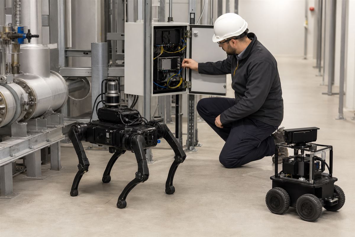
- Choose two representative robot types and list each sensor, connection, local workload, and evidence field.
- Run a controlled inspection capture with the fleet service available; verify that the right asset, robot, and observation are associated.
- Repeat with the fleet path unavailable. Confirm the designed local behavior, queued records, and operator-visible exception rather than assuming a silent retry is acceptable.
- Restore the link and validate reconciliation: no missing, duplicated, or misassigned evidence.
- Repeat in the installed enclosure, including cable routing, power-up and recovery, thermal conditions, and service access.
Failure modes worth discussing early
| Failure mode | What it can hide | Early check |
|---|---|---|
| Shared asset label is inconsistent | Two robots create records that appear to describe different objects. | Use an explicit asset-ID and evidence schema before the first field run. |
| One robot loses site connectivity | Local observations are dropped or a mission changes without a trace. | Test the defined disconnected state and reconciliation procedure. |
| Camera route changes during installation | Bench behavior cannot be reproduced on the deployed robot. | Record physical interfaces, harness routing, and calibration ownership in the installation review. |
| Fleet service receives ambiguous files | Operators cannot determine which robot or mission produced a finding. | Require robot, mission, asset, capture, and retry metadata in the handoff. |
FAQ
Should a multi-robot inspection fleet use one central computer?
A central service can coordinate and aggregate evidence, but each robot should have a defined local path for the sensing and inspection work it must perform during a temporary loss of fleet access.
Does a robot-side edge AI computer replace the robot controller?
No. It can support perception, inference, sensor processing, communication, and higher-level robot software. It does not automatically assume dedicated motion, drive, or safety responsibilities.
What should a supplier inquiry include?
Share the robot types, sensor interfaces, intended local workloads, operating enclosure, power and thermal constraints, required communication paths, evidence schema, and the recovery behavior expected after a disrupted connection.