English
 Español
 Português
 Deutsch
 한국어
 日本語
 Italiano
 Français
 العربية
 Türkçe

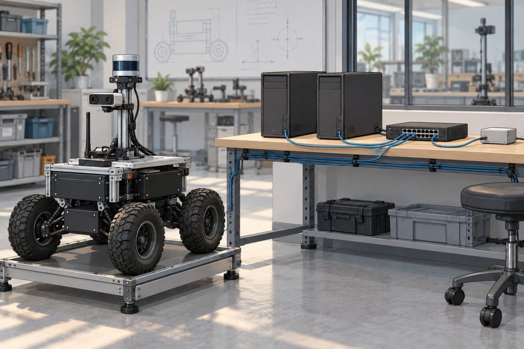
Before fusing ROS 2 sensor streams from different computers, document what each timestamp means, establish a shared time reference, and measure timing uncertainty through startup, full workload and recovery. A visible topic or a synchronized host clock does not prove that camera exposure and lidar sampling are aligned. The acceptance deliverable is a timestamp map, a justified error budget and a repeatable pass/fail record for the installed robot.
Map the timestamp before measuring the offset
Start with the sensor driver and the fusion subscriber. For each stream, record the physical event being stamped, the clock that supplies the number and any conversion into the receiving host’s time. The ROS 2 Jazzy Image message definition says its header timestamp should be image acquisition time; verify that meaning in the selected driver rather than assuming it from the field name.
| Field | What to record | Evidence to request |
|---|---|---|
| Acquisition event | Exposure start, exposure midpoint, scan reference point or another defined event | Sensor and driver documentation, including exposure/scan mode |
| Original clock | Sensor-local counter, host system time or another reference; units and epoch | Clock topology and counter rollover/reset behavior |
| Conversion | Where offset/rate conversion occurs and which parameters it uses | Driver version, configuration and conversion logs |
| Consumer clock | Clock used by the fusion node and the intended live/replay mode | Launch parameters and clock-source checks |
Check use_sim_time for every participating node. ROS time can follow system time or an active simulated-time source; steady time serves a different purpose, such as local hardware timeouts. Do not subtract independently started steady-clock readings from separate computers. The ROS 2 clock design also describes backward time jumps, which matter when replay resets a timeline.
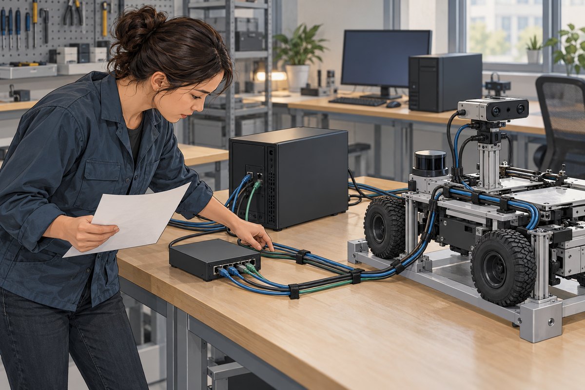
Choose a reference that the installed system can support
Draw the primary reference, every host and every sensor clock. State what should happen when the reference disappears. For an example of a robot-level NTP topology, Clearpath’s Humble networking documentation uses chrony with the robot’s primary computer as the source for its other computers. This is an architectural example, not an MScape software configuration.
If the timing budget requires evaluating PTP, check the exact network interfaces, drivers, switches and sensors. The linuxptp ptp4l manual distinguishes hardware and software timestamping and documents PTP hardware-clock requirements. An Ethernet port label alone does not establish that the complete path supports the intended mode. Synchronizing host clocks also does not trigger simultaneous sensor acquisition.
Capture clock evidence beside the sensor evidence
On Linux hosts already configured to use chrony, collect these read-only reports on each host throughout the same test interval. Installation and time-service configuration are separate integration tasks.
chronyc tracking
chronyc sources -v
Keep the host identity, collection time, selected source, synchronization state and full output. The chrony 4.8 command reference explains system-time correction, offset statistics, root delay and root dispersion. A small last-offset value is one observation; it cannot establish a guaranteed maximum error across a run. Source selection and uncertainty must remain visible.
Collect sensor sequence numbers, original timestamps, converted timestamps and subscriber arrival times alongside those reports. These expose different parts of the path. For delivery freshness after clock comparability is established, use the separate ROS 2 camera QoS and frame-age guide. Increasing a queue depth cannot resolve an unknown clock conversion.
Build a timing budget with explicit assumptions
Consider a hypothetical acceptance target: two streams must represent acquisition events within 3 ms. Suppose independent validation establishes bounds of 0.4 ms for host A and 0.6 ms for host B relative to the same reference. Their relative host-clock uncertainty is conservatively at most 1.0 ms, by adding the bounds. These inputs are assumptions, not measured N210 performance or values inferred from a single chrony report.
If the application accepts pairs whose converted timestamps differ by at most 1 ms, then at most 1 ms remains for combined acquisition-event and timestamp-conversion uncertainty: 3 − 1 − 0.4 − 0.6 = 1 ms. This simple worst-case allocation requires valid bounds over the whole acceptance interval. It excludes calibration error and algorithmic estimation error.
Unknown sensor timestamp semantics leave the budget unresolved even if both hosts appear synchronized. To validate event alignment, use an independently observable common event or instrumented timing method supported by the sensors. Record the method’s own uncertainty. Comparing message arrival times alone mixes acquisition, transport and scheduling effects.
Accept startup, load and recovery as separate states
Set test duration, sampling interval, timing limits and permitted recovery time before running the installed workload. The following is a proposed acceptance protocol, not a report of completed tests. Perform fault scenarios on an isolated stationary rig with motion disabled.
| State | Evidence | Reject or hold acceptance when |
|---|---|---|
| Cold start | Reference availability, clock settling, first accepted sensor pair | Fusion accepts data before the agreed timing-valid condition |
| Concurrent workload | Clock reports, sensor alignment and conversion logs while inference, recording and network traffic run | Any validated bound or pairing limit is exceeded |
| Reference loss | Source-loss detection, elapsed holdover time and application response | The pipeline silently treats unbounded timestamps as valid |
| Reference recovery | Reselection, any clock discontinuity, stale-buffer handling and return-to-valid time | Old and new timelines are mixed or recovery exceeds the requirement |
| Host or sensor restart | Counter reset, conversion reinitialization and fresh timestamp mapping | A pre-restart conversion is reused without revalidation |
Save configuration hashes or version identifiers with the record. Separate an observed maximum from a justified bound, and state gaps in the sampling coverage. If the measurement method cannot resolve the required limit, the result is inconclusive.
Turn the record into a computer integration requirement
The N210 sensor-fusion evaluation guide connects timing evidence with sensor interfaces, workload and output ownership. Consider the MScape N210 robotics edge AI computer when evaluating that robot-side integration path. Confirm the exact hardware and software configuration against the required timing architecture; this procedure establishes no model-specific synchronization accuracy or PTP compatibility.
A computer change is insufficient when the unresolved issue is a sensor’s timestamp origin, trigger behavior or clock conversion. Resolve that dependency before selecting hardware around an assumed timing figure.
Send MScape your timing and sensor integration brief: robot application, camera count and other sensors, timestamp map, required alignment and recovery limits, control bus, concurrent compute/recording workload, power budget, deployment country and timeline. Include the acceptance record so the configuration discussion starts from a measurable requirement.