English
 Español
 Português
 Deutsch
 한국어
한국어 日本語
日本語 Italiano
 Français
 العربية
 Türkçe
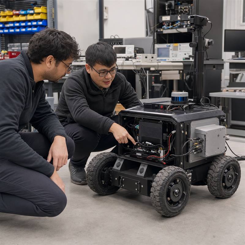
A rugged edge AI computer for a robot should be validated as part of an interface architecture, not selected only because its processor can run an AI demo. ROS 2, EtherCAT, and CAN FD can all appear in the same machine, but they carry different kinds of information and need clear ownership, cabling, software, and recovery tests before deployment.
Short answer
Start with a map of every sensor, compute workload, network, fieldbus, and dedicated control function. Use ROS 2 to organize the robot software and data flow where it fits the system; validate EtherCAT and CAN FD as the actual machine interfaces they are. A robotics edge AI computer can support perception, local inference, communications, and data handling, but it does not automatically become a robot or motion controller.
Why interface validation comes before a hardware shortlist
A bench setup often begins with one camera, one application process, and a convenient USB or Ethernet connection. A deployable robot can add multiple cameras, an IMU, lidar, motor-drive or vehicle-state networks, recording, remote diagnostics, power events, and a protected enclosure. The risk is rarely a single protocol name. It is an undocumented boundary: who produces the data, who owns the action, what happens after a restart, and how the machine behaves when an input is absent.
That is why a good selection brief starts with the machine rather than a generic port list. The MScape application cases provide useful autonomous-machine context, while the actual integration must be defined around the robot’s sensors, actuator architecture, and deployment environment.
Give each layer a clear job
| Layer | Typical responsibility | Validation question |
|---|---|---|
| Sensor and device inputs | Cameras, lidar, IMU, encoders, vehicle state, and other machine signals | Are connector type, bandwidth, timestamp assumptions, cable routing, and restart behavior recorded? |
| Robot-side edge AI computer | Perception, selected inference, sensor processing, logging, communications, and application services | Can the intended workload run with the complete sensor set inside the actual power, thermal, and enclosure constraints? |
| ROS 2 application layer | Nodes, message flow, lifecycle management, and integration of robot software components | What data contracts, namespaces, launch order, and recovery behavior are tested in the installed machine? |
| Dedicated actuator control and safety functions | Machine-specific low-level control, drive behavior, and safety responsibilities | Are authority, fault response, and safe-state behavior retained by the appropriate dedicated architecture? |
This separation matters even when a computer has Ethernet or fieldbus connectivity. Communication support can be valuable for an integrated robot architecture; it is not proof that the edge AI computer should take over dedicated actuator or safety responsibilities.
ROS 2, EtherCAT, and CAN FD: evaluate the boundary, not the label
| Technology | Useful question for an edge-AI evaluation | Common integration mistake |
|---|---|---|
| ROS 2 | Which sensor, perception, planning, and diagnostic components exchange data through the robot software architecture? | Assuming a successful demo launch proves lifecycle, logging, restart, or disconnected-operation behavior. |
| EtherCAT | Which machine subsystem owns the network, its master configuration, device discovery, and fault handling? | Calling any computer with a connection a complete motion-control solution without proving the dedicated architecture. |
| CAN FD | Which messages are needed from vehicle, battery, actuator, or sensor subsystems, and who owns their interpretation? | Leaving message ownership, isolation, termination, or recovery assumptions for late-stage integration. |
The exact software and electrical implementation depends on the robot. The practical review is the same: record the interface, data owner, consumer, refresh/recovery behavior, and validation evidence for every link. Keep high-level perception and decision workloads distinguishable from the dedicated architecture that owns low-level machine action.
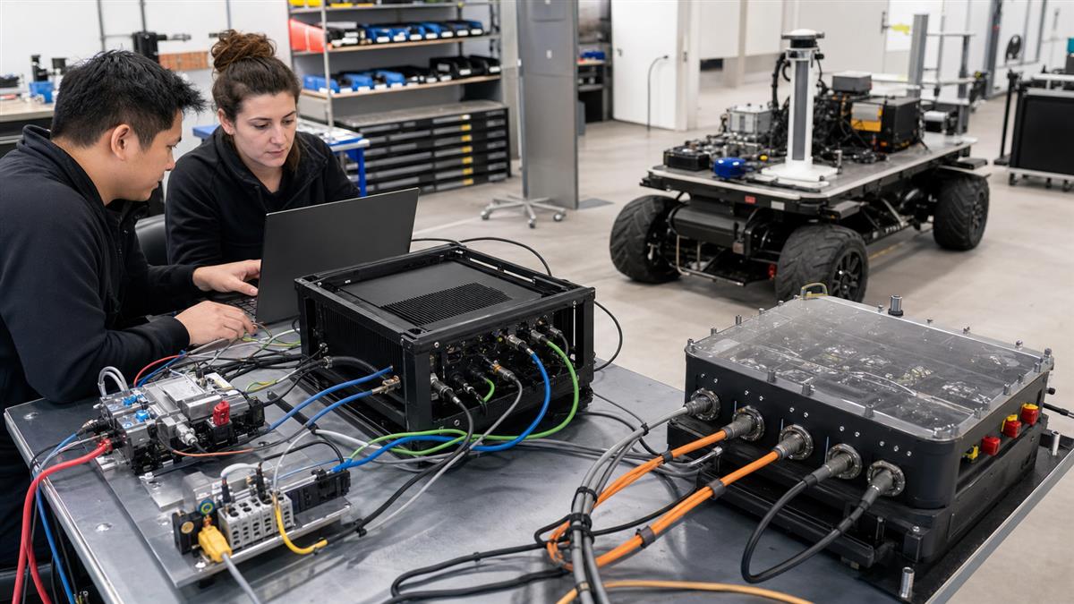
A useful bench makes sensor, compute, communications, power, and dedicated actuator-control paths visible as separate engineering responsibilities.
Build an interface-validation packet
Before comparing computers, create one packet shared by robotics, electrical, mechanical, software, and procurement teams. It should list sensor count and interfaces; intended ROS 2 nodes and data flows; Ethernet, EtherCAT, and CAN FD requirements; local workloads; expected log storage; power input behavior; enclosure and cooling constraints; and how each service is accessed in the field.
Worked scenario: a camera-rich mobile robot
Consider a mobile robot that gathers camera and lidar data, runs local perception, reports diagnostic state, and exchanges selected information with an existing machine architecture. The edge AI computer can host the perception and application workloads. The team then validates that cameras arrive reliably, local processes restart as designed, logs can be retrieved, and the machine’s dedicated control and safety responsibilities remain explicit. If a camera stream is lost or an application restarts, the intended degraded behavior should already be defined by the robot architecture鈥攏ot improvised during a site test.
Failure modes a specification sheet will not reveal
| Failure mode | Why it is missed | Earlier check |
|---|---|---|
| Interface count grows after the prototype | The initial rig has fewer sensors, shorter harnesses, and no service-access requirement | Validate the production-intent sensor map, routing, connector clearance, and expansion headroom. |
| Data flow works only in one startup order | The bench is manually started and rarely power-cycled | Test cold start, process restart, device reconnection, and log collection with the installed configuration. |
| Fieldbus responsibility is unclear | Protocol names substitute for a documented ownership model | Assign each network’s owner, interface, failure response, and test evidence before system integration. |
| Thermal or power constraints appear late | AI runs without the full sensor, recording, and enclosure load | Run representative workloads with the final harness, power source, enclosure, and cooling path. |
Where N Series hardware fits
After the interface packet is clear, N Series hardware can be evaluated as a robot-side computing path. The MScape N210 robotics edge AI computer is relevant when sensor fusion and industrial interconnect are central to the architecture. The MScape N203 multi-camera edge AI computer is a suitable path for camera-rich perception requirements. For a compact robot integration where CAN FD and connected embedded compute are material, assess the MScape N100 compact robotics edge AI computer against the complete interface and installation brief.
Do not select a model solely because it appears in a robot category. If the task is still a broader hardware shortlist, begin with the N Series product overview and the related robotics edge AI computer selection guide. If the project needs several direct camera inputs, move the evaluation toward N203; if it needs a more complex sensor-fusion and interconnect review, assess N210 instead.
Five-step installed-system validation
- Freeze the sensor, network, fieldbus, workload, and ownership map鈥攊ncluding planned additions.
- Verify device discovery, data flow, timestamps, logging, and process lifecycle with the installed harness.
- Run the representative workload with the intended power source, closed enclosure, cooling path, and storage behavior.
- Exercise defined degraded cases: missing sensor, reconnecting device, application restart, and controlled loss of remote connectivity.
- Review the evidence with software, electrical, mechanical, machine-control, safety, and procurement stakeholders before release.
FAQ
Does ROS 2 turn an edge AI computer into a robot controller?
No. ROS 2 can be part of the robot software architecture. It does not, by itself, assign or prove low-level control and safety responsibilities. Those remain design decisions for the complete machine.
Should EtherCAT and CAN FD be tested only after the AI model works?
No. Interface, ownership, restart, and fault-handling assumptions should be validated early. A successful inference demonstration does not replace installed-system evidence.
What should an inquiry include?
Share the robot type, camera count, sensor stack, ROS 2 environment where relevant, EtherCAT/CAN FD interface needs, control-boundary definition, intended local workloads, power budget, enclosure constraints, and deployment timeline.
Start with the real interface map
Contact MScape with your robot type, camera count, sensor stack, industrial communications requirements, control-bus boundary, compute workload, power budget, and deployment timeline. That gives an N Series hardware evaluation a technically useful starting point.