English
 Español
 Português
 Deutsch
 한국어
한국어 日本語
日本語 Italiano
 Français
 العربية
 Türkçe
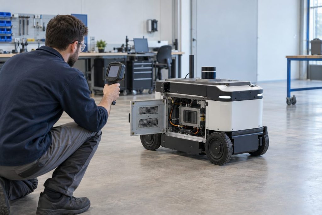
Cover image illustrates a validation workflow; it does not show an MScape product or a completed test.
Thermal validation for a robotics edge AI computer should test the complete installed robot build, not a bare computer on an open bench. The useful result is evidence that the perception, inference, sensor and communication workload can run in the intended enclosure, mounting position and service condition without creating an unexamined deployment risk.
Why an open-bench result is not a robot result
A development bench often has easy airflow, short cables and an accessible power supply. A mobile robot or inspection machine may place the computer near batteries, motors, cameras, protective panels and cable bundles. The thermal path changes when a panel closes, a connector is strain-relieved or the robot carries its normal payload.
This is not an argument for treating every deployment as the same. It is a reason to make the physical installation part of the selection evidence. The test should represent the workload that matters: camera acquisition, preprocessing, inference, logging, sensor handling and the communications that remain active during the mission. Dedicated motion and safety functions should stay within their own designed systems; this guide concerns robot-side AI computing and its installed operating context.
NVIDIA documents software-visible power and thermal management for the Jetson Orin family in its Jetson Linux developer guide. The final computer’s thermal path also depends on its carrier, enclosure and robot installation, so preserve the tested software and physical configuration in the record.
Define the thermal validation question first
Before comparing hardware, write one short test statement: “Can this installed robot-side computer support this named software and sensor configuration in this enclosure and operating scenario?” That sentence forces the team to identify what is being proven and what has not yet been tested.
| Test element | What to represent | Evidence to keep |
|---|---|---|
| Workload | The intended perception, inference, recording and communications mix—not a synthetic task alone. | Software revision, model revision and enabled services. |
| Installation | Production-intent mounting, enclosure panels, cable routing and nearby heat sources. | Photos of mounting and cable path; enclosure revision. |
| Power path | The robot’s intended source and normal power-up, idle and operating states. | Power-system configuration and observed restart behavior. |
| Mission scenario | A repeatable route, inspection sequence or picking cycle that drives the relevant sensors. | Test script, ambient conditions and run log. |
Run a validation sequence that exposes installed-system issues
1. Freeze a representative build
Lock the application image, model version, sensor configuration and enclosure revision for the test. Changing several variables during a run makes the result difficult to repeat or compare. If a later revision is necessary, record it as a new test condition rather than silently replacing the original.
2. Start with a complete physical inspection
Confirm that mounting hardware, cable bends, connectors, access panels and planned airflow match the engineering intent. Check whether a service technician can reach the required connections without disturbing unrelated assemblies. A computer that only works when the enclosure is open has not passed an installed-build check.
3. Exercise the real workload long enough to settle
Run the intended robot mission or a controlled equivalent with real sensor traffic. Observe the whole chain rather than one temperature readout: camera availability, inference service health, storage behavior, communication continuity and the robot’s ability to return to a known operating state after a planned stop. Record conditions and observations so another team can repeat the test.
4. Check recovery and serviceability
Deliberately use approved restart and recovery procedures. Then ask practical questions: Is the source of a fault diagnosable? Can the computer be accessed safely for service? Does the configuration record identify the hardware and software combination? These questions turn a one-time lab observation into deployable engineering evidence.
Common failure patterns—and what they reveal
| Observed pattern | Likely investigation direction | Better next step |
|---|---|---|
| Bench test is stable; closed robot build behaves differently | Installation changed the thermal, power or cable environment. | Repeat with production-intent enclosure and routing; document the difference. |
| Only a simplified demo works | The evaluation did not include the sustained sensor and software mix. | Use a representative mission and preserve the workload definition. |
| Issue appears after a service change | Build identity or physical reassembly was not controlled. | Record revision, mounting, cabling and software as one configuration. |
| Fault recovery is unclear | The computer may be physically installed, but operational support has not been designed. | Test approved restart, logging and access procedures before a pilot expands. |
Turn thermal evidence into a hardware decision
After the engineering reasoning is clear, use it to narrow hardware paths. The MScape N203 and MScape N210 are two relevant robot-side computing configurations. Compare their actual interface, harness and power requirements; both still need installed-build thermal validation.
If the workload, sensor density or physical constraints materially change, revisit the selection through the N Series product overview. For application context, see robotics application cases. The related guide on moving from a development kit to a deployable robot computer helps frame the broader transition.