English
 Español
 Português
 Deutsch
 한국어
 日本語
 Italiano
 Français
 العربية
 Türkçe

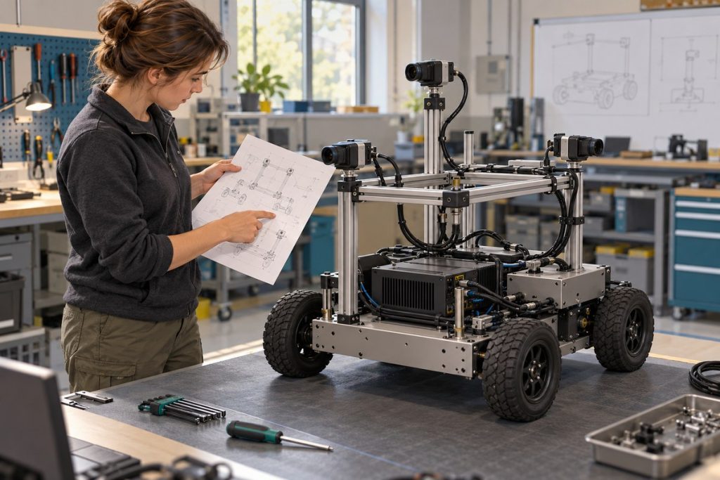
Accept a recovered GMSL2 camera stream only after checking its physical identity, capture mode, fresh-frame delivery and effect on the other required streams. Time recovery to the point where the robot application can use the data again, rather than the first returning image. Agree the permitted interruption and restoration procedure with the camera and computer suppliers before testing. A cable connector or a working preview does not establish hot-plug support or automatic recovery.
This procedure helps robotics integrators write a camera-recovery acceptance record. It assumes a supplier-confirmed camera chain and an approved, stationary test setup. It provides a proposed test method, not measured product results.
Freeze the camera chain and its observation points
Record the camera part number and revision, serializer, harness, computer configuration, software image, driver package, capture API and requested mode. Ask the supplier to identify which components and settings the recovery procedure changes. A process restart, camera power cycle and complete computer reboot are different restoration operations; record them separately.
NVIDIA’s Jetson Linux r36.4.4 GMSL reference framework configures virtual channels across the deserializer and receiver. Its reference setup uses specific sensors and SerDes components. It explains why a complete mapping matters; it does not validate a different vendor’s camera chain.
Make one identity row per view: physical mounting position, camera serial or supplier-supported identifier, cable and input, logical stream name, and calibration record. Do not accept a device path alone as the view identity. Where serial identification is unavailable, document a repeatable visual identification test and its limits.
Define a return-to-service gate
Give the test observer access to capture-level evidence and application-level evidence. NVIDIA distinguishes direct V4L2 access from the Argus/ISP camera path in its camera software development guide. A basic capture result therefore needs a separate check through the API and processing path the robot actually uses.
| Observed state | Evidence to collect | Exit condition proposed for the test |
|---|---|---|
| Baseline usable | All required views, identities, modes and application outputs before the event | Baseline matches the approved configuration |
| Stream unavailable | Event time, detection time, fault indication and other-stream status | The application exposes the missing input and follows its agreed degraded behaviour |
| Frames returning | First frame, identity, mode, capture metadata and stale-data check | Correct view and current data are demonstrated |
| Requalification | A predefined observation window under the intended workload | Every required criterion holds throughout that window |
| Usable again | Application output, affected views, recovery operation and complete event log | Acceptance owner signs off, or records an explicit failure |
Define the observation-window length and allowed frame gaps before starting. Choose these from the robot task and supplier capabilities. A universal recovery-time limit would hide differences between a recording robot, a navigation pipeline and an inspection capture sequence.
Measure usable recovery, including requalification
Use one monotonic observer clock for event timing. Keep this recovery measurement separate from sensor exposure synchronization. Log the approved interruption, application fault detection, first returning frame, completion of requalification and restoration of usable application output.
Hypothetical timing example: an interruption occurs at 10.000 s; the application reports it at 10.180 s; the first correct fresh frame returns at 12.400 s; a proposed 1.000 s requalification window finishes at 13.400 s, when the application also becomes usable. Detection delay is 0.180 s. First-frame return takes 2.400 s. Usable recovery takes 3.400 s. Reporting only 2.400 s omits one second required by this assumed acceptance gate. These are illustrative inputs, not an N203 benchmark or recommended limit.
For each run, save the baseline identifier, event type, operation used, five event times, identity check, frame/error evidence, other-stream effects and pass/fail reason. Keep failed runs. Record retries and operator actions rather than restarting the stopwatch after an unsuccessful attempt.
Prove freshness and inspect the shared failure boundary
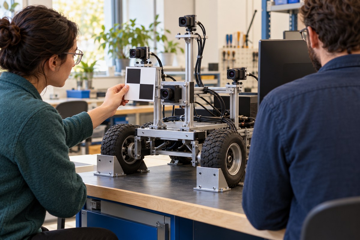
During the stationary bench test, move a patterned target within the selected camera’s view and verify that the returned images reflect the new scene. Repeat for each physical view so a relabelled stream cannot pass unnoticed. Match the result to the intended calibration file before enabling downstream use.
The Linux V4L2 buffer documentation defines sequence, timestamp and error metadata. It also explains that the driver determines timestamp clock and capture point. Use the fields your driver exposes, but do not interpret a counter or timestamp alone as proof of fresh sensor exposure or absence of upstream loss.
Observe every required stream during a single-stream interruption. Record whether unaffected views continue, pause or restart. A recovery operation that restores one view while disrupting the others may violate the application’s acceptance criteria. Treat the allowable scope of disruption as a requirement to confirm and test.
For software stream restarts, the V4L2 STREAMON/STREAMOFF API describes queue removal on stream-off. Include application queues in the recovery review as well. Driver queue behaviour does not establish that the robot’s processing pipeline has discarded its old images.
Choose only supported fault and restoration operations
Start with the supplier-approved process stop/start and normal startup cases. Test missing-camera startup, sensor power cycling or cable interruption only when the electrical design and supplier procedure explicitly permit them. Do not improvise live coax disconnection. Keep motion disabled and use the project’s established safety arrangements.
If restoration requires a reboot, record that dependency and its full application downtime. If a fault cannot be detected or fresh data cannot be established, leave the state unavailable. Repeating the accepted procedure after a camera, harness, driver or image change makes the evidence traceable to the delivered configuration.
Use the record in an N203 evaluation
The MScape N203 camera-rich robotics computer offers NVIDIA Jetson AGX Orin options and eight GMSL2 inputs. Those inputs do not establish support for a particular camera, simultaneous mode combination, hot-plug operation or recovery duration. If your project requires a recovery behaviour that remains unverified, keep N203 selection conditional on resolving it.
Use the N203 camera-chain compatibility worksheet to settle the underlying hardware and software dependencies first. Then send MScape a camera-recovery requirement brief: robot type, camera count and part numbers, other sensors, capture modes, control bus, compute target, permitted restoration operation, downtime requirement, power budget, environment, quantity, delivery country and deployment timeline. Attach the identity map and acceptance log so the discussion can address the actual integration boundary.