English
 Español
 Português
 Deutsch
 한국어
한국어 日本語
日本語 Italiano
 Français
 العربية
 Türkçe
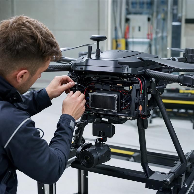
A drone companion computer should be selected around the cameras, software workload and aircraft installation limits, not its headline AI rating. First assign flight-control responsibilities. Then check sensor connections, total installed mass, source-side power and cooling. Finally, test what happens when the companion computer or a sensor stops responding. The worksheets below help turn those requirements into a hardware shortlist and an integration test plan.
Separate companion computing from flight control
PX4 describes companion computers as separate onboard computers used alongside a flight controller. Its architecture puts core flight and safety code on the flight controller and typically uses Linux for companion applications. ArduPilot describes MAVLink communication between the two for flight data and higher-level tasks.
For your aircraft, document which external commands the flight controller accepts and what it does if they stop. A working communication link alone does not establish a safe command path. The following worksheet is an engineering planning aid, not a flight-safety approval.
| Owner | Assign before integration | Record as evidence |
|---|---|---|
| Flight controller | Stabilisation, actuator outputs, flight modes, accepted external commands and loss response | Selected firmware, mode configuration, command limits and relevant flight-controller logs |
| Companion computer | Camera processing, inference, recording and higher-level mission software | Process-health checks, output timestamps and restart policy |
| Sensor pipeline | Camera identity, calibration, timestamps and treatment of stale observations | Calibration version, frame-loss log and missing-input response |
| Ground connection | Functions requiring a live connection versus those that must continue locally | Defined disconnected behaviour and locally retained diagnostics |
Reject unsuitable hardware before comparing AI performance
Start with installation constraints. Include the computer, mounting, cables, converters and cooling hardware in the mass and space allowance. Check connector clearance and service access. If the aircraft cannot accommodate that assembly or remove its heat, a faster module does not solve the mismatch.
Next list every camera interface, required stream format and recording path. Run camera capture, preprocessing, inference, recording and communication together when measuring the workload. A result from inference alone is not evidence that the complete onboard application will meet its timing requirements.
The MScape Product Brochure 2026.7.V2 provides the following shortlist inputs. They do not certify either model for an aircraft or establish compatibility with a particular autopilot or camera.
| Item | N201 | N203 |
|---|---|---|
| Compute options | NVIDIA Jetson AGX Orin, 32 GB or 64 GB | NVIDIA Jetson AGX Orin, 32 GB or 64 GB |
| GMSL2 listed in brochure | No GMSL2 input listed; confirm the required camera connection separately | 8 × GMSL2; exact camera and software combination still requires confirmation |
| External Ethernet / USB 3.0 Type-A | 3 × Gigabit Ethernet / 6 × USB 3.0 | 2 × Gigabit Ethernet / 4 × USB 3.0 |
| Input voltage | DC 9–48 V | DC 9–48 V |
| Listed mass and dimensions | 0.76 kg; 118 × 126 × 42 mm | 0.62 kg; 118 × 126 × 46 mm |
Both models also list one Gigabit Ethernet pin header. A header is not an additional ready-to-connect external socket. Check the quoted configuration and harness requirements before freezing the design.
Consider the N201 embedded AI computer when its Ethernet and USB layout matches the sensor plan. Consider the N203 multi-camera computer when direct GMSL2 input is a governing requirement. Exclude either candidate if installed mass, power, cooling or unconfirmed interface support makes it unsuitable.
Calculate the payload power budget at the source
An input-voltage range is not a power-consumption specification. Obtain measured average, peak and startup demand for the selected computer configuration and workload. Keep the payload calculation separate from propulsion and the rest of the aircraft electrical budget.
Illustrative example only: these are not N201 or N203 specifications. Assume a computer draws 45 W, two cameras draw 6 W each, a modem draws 8 W and other payload devices draw 5 W.
- Payload output demand: 45 + (2 × 6) + 8 + 5 = 70 W.
- Assume all these loads use one conversion path with 90% efficiency: 70 / 0.90 = 77.8 W at its input.
- With a separate, illustrative 20% sizing allowance: 77.8 × 1.20 = 93.3 W.
- At a hypothetical 24 V source: 93.3 / 24 = 3.89 A for this allocation.
Replace the assumptions with measurements and the converter’s efficiency at the actual load. For several power rails, calculate each conversion path separately. Neither this allowance nor the calculated current verifies startup transients, wiring, protection, minimum-voltage operation or battery endurance.
Verify failure behaviour before flight integration
Set acceptance limits with the aircraft engineering team before testing. Begin in simulation or on an appropriately secured integration bench. Do not conduct deliberate failure injection on an airborne vehicle on the basis of this article.
| Check | Controlled test | Keep this record |
|---|---|---|
| Startup | Use the intended power and service-start sequence | Boot time, sensor availability and communication readiness |
| Link or application loss | Simulate missing companion output in each relevant mode | Configured response, detection delay and recovery authorisation |
| Missing or stale camera data | Use a supported fault simulation; do not assume live cable removal is safe | Detection, rejected observations and restart behaviour |
| Concurrent load and heat | Run the deployed workload in the intended enclosure and cooling arrangement | Temperatures, throttling, processing delay, dropped frames and errors |
| Storage and power recovery | Exercise approved low-space and power-cycle cases | Retained logs, data integrity and return to the defined state |
Use the robotics interface-validation guide to organise the wider connection and recovery plan. Flight-controller documentation and the aircraft’s safety process remain authoritative for flight behaviour.
Send the constraints with your inquiry
For an N201 or N203 evaluation, share the aircraft application, camera models, flight stack and link, software workload, supply and power allowance, cooling arrangement, installed mass limit, quantity and delivery country through the MScape inquiry page.
MScape N Series products are not available for delivery to the United States or Canada.