English
 Español
 Português
 Deutsch
 한국어
한국어 日本語
日本語 Italiano
 Français
 العربية
 Türkçe
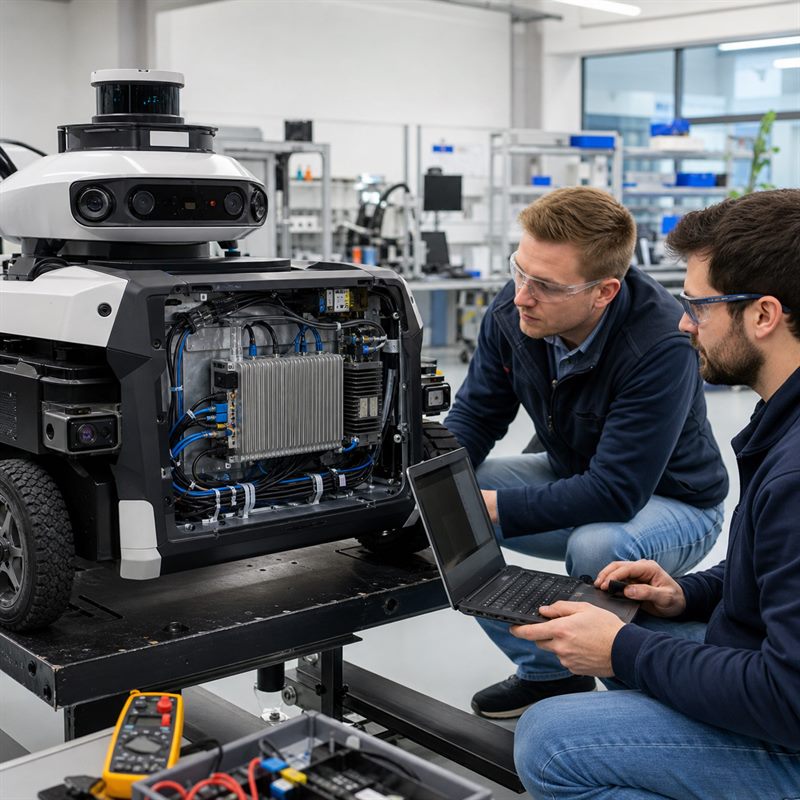
Short answer: an embedded AI computer for robots should be selected as part of an onboard architecture, not as an isolated processor. Start with sensor paths, concurrent AI workloads, the boundary with motion and safety control, remote connectivity, and the real power and thermal envelope. Then choose a complete computer whose interfaces and packaging can survive the move from bench prototype to deployed machine.
Why a Working AI Prototype Can Still Fail on the Robot
A perception model may run on a bench while the robot remains far from deployment. The common gap is not only compute. It is the difference between a convenient development setup and a maintainable robot-side system: camera cables must reach protected connectors, the battery must tolerate startup and peak load, heat must leave an enclosed compartment, logs must survive a power event, and a technician must be able to diagnose the machine without rebuilding the bench.
NVIDIA explicitly describes Jetson developer kits as tools for development and pre-production testing rather than production systems. That does not make a developer kit unsuitable for prototyping; it means the production decision must cover the carrier, storage, power input, cooling, enclosure, connectors, and service workflow around the Jetson module. The practical question is therefore not “Which board runs the model?” but “Which embedded AI computer for robots carries the complete workload inside this machine?”
Use a Five-Layer Robot-Side Compute Architecture
A useful design review separates the system into five layers. This prevents a high headline AI figure from hiding an interface, control-boundary, or deployment problem.
| Architecture layer | Decisions to document | Typical failure if ignored |
|---|---|---|
| 1. Sensor ingress | Camera types and count, lidar or other sensors, data rates, cable length, synchronization method, and sensor power. | The computer has enough compute but cannot accept or reliably transport the real sensor streams. |
| 2. Local AI workload | Models, resolution, frame rate, preprocessing, concurrency, memory, recording, and software growth. | A benchmark fits, but the complete pipeline throttles, swaps, or drops data. |
| 3. Robot and control boundary | Messages exchanged with the controller, required Ethernet, CAN, serial, or GPIO interfaces, and ownership of motion and safety functions. | Perception and control responsibilities become ambiguous during integration and validation. |
| 4. Connectivity and operations | Wi-Fi, cellular, fleet connection, logs, updates, remote diagnostics, and behavior when the network disappears. | The robot depends on a link that is unavailable in the real operating area. |
| 5. Physical deployment | DC input, transient protection, startup behavior, cooling path, mounting, vibration, connector retention, and service access. | The bench system works, but the enclosed mobile system resets, overheats, or is difficult to maintain. |
Worked Solution: Compact Connected Inspection Robot
Consider a small wheeled inspection robot with two compatible cameras, a lidar, local object detection, event recording, vehicle telemetry, and remote review. A practical design keeps perception and recording on the robot so core behavior does not depend on continuous cloud access. Ethernet or USB carries the selected camera streams; storage holds logs and evidence; the AI computer sends compact results to the robot’s defined control layer; and Wi-Fi or cellular connectivity carries status, selected events, and updates.
The control boundary must stay explicit. CAN FD, serial, GPIO, or Ethernet connectivity can move state and commands between subsystems, but interface availability does not automatically make the AI computer a motion or safety controller. The robot architecture should identify which dedicated components own actuator coordination, emergency behavior, and protective functions, then specify exactly what data crosses into and out of the AI workload.
This design also exposes questions that a product page cannot answer for you. Are the Ethernet cameras powered separately? Is peak battery voltage inside the computer’s input range? Can the enclosure remove heat at the chosen workload? What happens to recorded data during an abrupt shutdown? Can the software recover if a camera or network link disappears? These questions turn a component shortlist into a testable deployment plan.
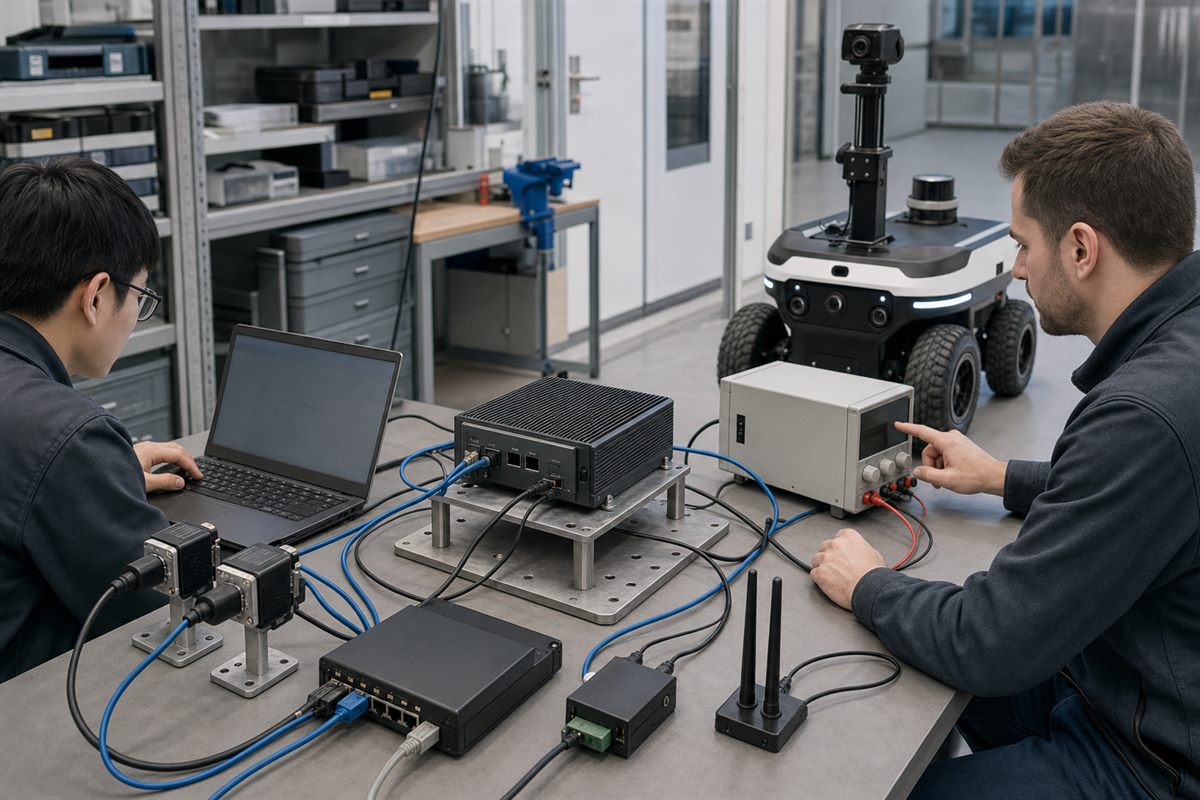
A robot-side compute design should be validated as a complete path: sensors, network, power, storage, thermal behavior, software recovery, and connection to the robot.
How to Size Compute Without Letting TOPS Make the Decision
TOPS is a capability indicator, not an application result. Model precision, memory traffic, preprocessing, video decode, CPU work, accelerator support, and simultaneous pipelines all affect the deployed outcome. Build a workload manifest before comparing computers.
Test capture, decode, preprocessing, inference, post-processing, logging, and communications together. Record sustained behavior after the system reaches thermal equilibrium.
Account for diagnostics, security updates, new sensors, and model changes. Headroom should come from a roadmap, not an arbitrary percentage.
Estimate model memory, buffers, concurrent processes, log volume, write endurance, and recovery after power interruption.
A higher module power mode also changes the board, supply, and thermal requirements. Validate the exact configuration that will ship.
NVIDIA’s current Jetson documentation likewise connects higher Orin NX power modes with carrier-board and thermal requirements. The wider lesson applies to any robot computer: performance configuration, power delivery, and cooling are one engineering decision.
Where the MScape N201 Fits—and When to Choose Another Path
The current N201 English datasheet lists NVIDIA Jetson AGX Orin 32 GB and 64 GB options, 1 TB industrial NVMe storage with power-loss protection, three Gigabit Ethernet ports, six USB 3.0 ports, two CAN FD channels, Wi-Fi and optional 5G connectivity, and a 9–36 V DC input. It lists a 118 × 126 × 52 mm enclosure and a weight of 0.93 kg. Those are useful facts for a compact connected robot architecture, but the final fit still depends on workload tests, sensor compatibility, installation, and environmental validation.
The MScape N201 embedded AI computer is therefore a credible evaluation path when the robot needs substantial local AI compute, general-purpose Ethernet and USB sensor connectivity, onboard storage, and remote communications in a compact complete computer. It should not be selected merely because the model can run once on an AGX Orin module.
Choose a different path when the architecture says so. A camera-rich robot that requires direct GMSL2 inputs should evaluate the N203 multi-camera edge AI computer. A program centered on larger models or heavier concurrent workloads may need the N1000 path. The N Series overview is the better starting point when sensor topology and workload are not yet stable.
Practical selection rule
Select the robot-side computer after writing a one-page architecture brief: robot type, sensor list, concurrent workloads, controller boundary, required interfaces, power source, enclosure and cooling plan, operating environment, and remote-service strategy. If a candidate cannot be traced to that brief, it is not yet an engineering choice.
Validation Plan Before the Pilot Build
- Freeze the pilot workload: record models, sensor formats, rates, precision, memory use, logging, and network traffic.
- Run an interface bench: connect the intended sensors and controller interface with production-like cables and power arrangements.
- Test power and thermal behavior: exercise startup, sustained load, enclosure airflow, and controlled shutdown or recovery.
- Inject faults: disconnect a camera, interrupt the network, fill storage, and restart after an unexpected power event.
- Review serviceability: confirm mounting, cable access, software update, log retrieval, replacement, and configuration recovery.
For a broader selection workflow, see MScape’s N Series robotics edge AI computer guide. The robotics application cases can also help frame the machine type before a hardware discussion.
FAQ
What is an embedded AI computer for robots?
It is a complete robot-side computer that runs local AI and sensor-processing workloads while fitting the machine’s interface, power, thermal, mechanical, and service constraints. It is more than the AI module alone.
Should a robot team choose compute before cameras and sensors?
No. Sensor type, count, interface, data rate, synchronization, and power method shape the computer choice. Define the sensor topology and concurrent workload together.
Does an embedded AI computer replace the robot controller?
Not automatically. It can provide perception, inference, planning inputs, logging, and communications, while the defined controller and safety components retain their assigned motion and protective roles.
What evidence should a buyer request?
Request the current datasheet, interface details, supported software baseline, power and environmental limits, storage configuration, mechanical drawing, validation scope, and a workload-based integration review.
Turn the Robot Brief into a Compute Shortlist
Use the MScape inquiry page to share your robot type, camera count, sensor stack, control bus, compute target, power budget, enclosure constraints, and deployment timeline. That information allows the engineering discussion to begin with the real architecture rather than a generic product list.